Unlock instant, AI-driven research and patent intelligence for your innovation.

Variable Length Bill Path

一种纸币处理、纸币的技术,应用在纸币处理系统领域,能够解决降低自动系统可靠性、增加纸币卡纸等问题

Inactive Publication Date: 2016-07-06
CRANE CANADA
View PDF7 Cites 0 Cited by
  • Summary
  • Abstract
  • Description
  • Claims
  • Application Information

AI Technical Summary

Problems solved by technology

The problem of high reliability is a difficult one because the system handles banknotes of widely varying quality
Switching points along the drive path increase the potential for banknote jams, which reduce the reliability of automated systems

Method used


Image

  • Variable Length Bill Path
  • Variable Length Bill Path
  • Variable Length Bill Path

Examples


Embodiment Construction

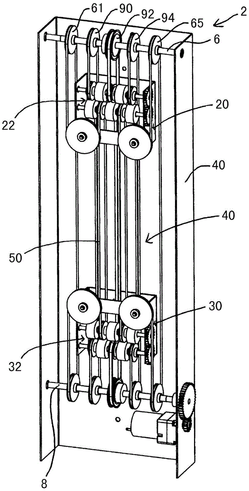
[0028] Figure 1~3 The banknote drive 2 shown in FIG. 2 comprises a frame 4 comprising a top shaft 6 and a bottom shaft 8 having a series of belt drive rollers or idler rollers connected to each other on the shaft. The top shaft 6 contains five wheels 61 , 90 , 92 , 94 and 65 and the bottom shaft 8 contains five wheels 67 , 110 , 112 , 114 and 69 . Outer wheels 61,67 and 65,69 form part of the path for front belts (frontbelts) 44 and 46 (see figure 2 ). These belts contain return paths located outside the transport racks, these will be explained later. Wheels 90 , 92 , 94 and wheels 110 , 112 , 113 are used for rear belts 50 , 52 and 54 .

[0029] A preferred belt drive arrangement 40 includes a first movable carriage 20 forming a first access 22 and a second movable carriage 30 forming a second access 32 . The first movable transport frame 20 and the second movable transport frame 30 move along the length (direction) of the banknote driving device, essentially moving tow...


PUM


Abstract

A variable length banknote drive path is advantageously used to provide a continuous drive path between components of an automated payment system. The banknote drive path includes at least a first inlet / outlet for receiving or outputting banknotes from the payment system and a movable second inlet / outlet for connecting with components provided along the drive path. With this arrangement the second inlet / outlet moves to provide a continuous drive path between components exchanging banknotes.

Description

[0001] This application is a divisional application of the following application: [0002] Filing date of the original application: February 10, 2011 [0003] The application number of the original application: 201180009325.0 [0004] Title of Invention of Original Application: Banknote Path of Variable Length technical field [0005] The invention relates to a banknote processing system. Background technique [0006] A number of automated systems are used to accept banknotes for payment and to process banknotes efficiently, either storing them in equipment or temporarily storing them in banknote accumulators. The banknotes stored in the hopper can be used for settlement in future monetary transactions. Typically, these banknote processing systems include a banknote validator (banknote validator), which is used to judge the authenticity of the banknotes, so as to decide whether to accept or reject the banknotes. If the banknote is accepted, it will be transported to the ...

Claims


Application Information

Patent Timeline
Patent Type & Authority Applications(China)
IPC IPC(8): G07D11/00B65H29/12B65H5/02G07D7/00G07D11/12
CPCG07D11/16B65H5/023B65H29/12B65H2301/4474B65H2402/10B65H2404/2613B65H2701/1912B65H2220/01B65H2220/02
Inventor 德米特罗·叶尔莫连科亚历山大·奥尼先科帕维尔·拉比诺维奇安德里·基谢廖夫
Owner CRANE CANADA
Features
  • R&D
  • Intellectual Property
  • Life Sciences
  • Materials
  • Tech Scout
  • Unparalleled Data Quality
  • Higher Quality Content
  • 60% Fewer Hallucinations
Learn More