Variable length electrodes for delivery of irrigated ablation

a technology of irrigated ablation and electrodes, which is applied in the field of variable length electrodes and conductive elements, can solve the problems of non-conductive lesion, blocked electrical pathways within the tissue, and insufficient function of electrical signals

Inactive Publication Date: 2005-07-12
MEDTRONIC INC
View PDF44 Cites 153 Cited by
  • Summary
  • Abstract
  • Description
  • Claims
  • Application Information

AI Technical Summary

Problems solved by technology

Occasionally, these electrical signals do not function properly.
The scar tissue resulting from the procedure results in a non-conductive lesion.
Lower levels of energy are used to cause cell damage but leave the structure intact so that electrical pathways are blocked within the tissue.
Undesirable consequences of overheating include the excessive coagulation of blood and the unintended destruction of healthy tissue adjacent the ablation site.
This requires a separate device that may not deliver irrigation as site-specifically as desired.
Furthermore, there is relatively high hydraulic impedance to saline flow at the distal end (towards ablation site) of a typical ablation device.
Additionally, there may also be difficulties with electrical impedance to saline flow in a typical ablation device.
Electrical flow may, therefore, occur preferentially towards the bridge and yield unreliable ablation.
Irrigation fluid may also not be evenly distributed along a single electrode because of the impedance factors described above.
Uneven distribution of fluid may result in an uneven lesion.
The electrode may contact the surface of the target tissue in these unirrigated areas, causing sticking or even charring.
Additionally, longer electrodes are sometimes desired to create longer lesions.
This results in greater fluid flow from the proximal end than the distal end and thus irrigation is unevenly distributed which may result in sticking of the ablated tissue to the electrode.

Method used


Image

  • Variable length electrodes for delivery of irrigated ablation
  • Variable length electrodes for delivery of irrigated ablation
  • Variable length electrodes for delivery of irrigated ablation

Examples


second embodiment

[0057]FIG. 8 shows a schematic view of a cross-section of a variable length electrode in accordance with the present invention. Conductive element 822 may be for example a double wound coil or spring as described above. Irrigating fluid may be flowed through the lumen 824 of electrode 822. Support element 833 may be for example a slotted tube. Such a slotted tube 833 may be any suitable material that may provide additional structural integrity to conductive element 822. The slotted tube 833 has an opening or slot 834. Preferably this opening 834 may run the length of an entire conductive element 822. This opening 834 may also run the length of an exposed section of a conductive element 822 which has been exposed in a manner as described in the above embodiments. This opening 834 may preferably face a surface of the tissue 860 to be ablated. As shown in FIG. 8, insulating material 832 may cover all of conductive element 822. Insulating material 832 may also cover slotted tube 833. In...

third embodiment

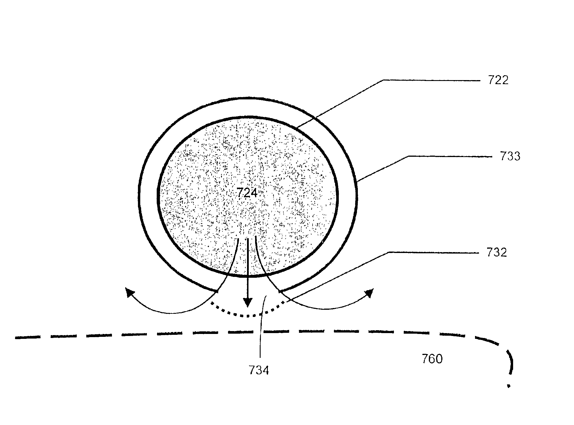
[0058]FIG. 9 shows a schematic view of a cross-section of a variable length electrode in accordance with the present invention. Conductive element 922 may be a slotted tube that also serves as a support element. Irrigating fluid may be flowed through the lumen 924 of electrode 922. The slotted tube 922 has an opening or slot 934. Preferably this opening 934 may run the length of an entire conductive element 922. This opening 934 may also run the length of an exposed section of a conductive element 922 which may be exposed in a manner as described in the above embodiments. This opening 934 may preferably face a surface of the tissue 960 to be ablated. As shown in FIG. 9, insulating material 932 may cover all of conductive element 922. Insulating material 932 may be for example a microporous non-conductive component. Such a microporous non-conductive component may be manufactured from a material such as silicone, PTFE, Dacron fabric or solvent-precipitated polyurethane. Preferably, th...

fourth embodiment

[0059]FIG. 10 shows a schematic view of a cross-section of a variable length electrode in accordance with the present invention. Conductive element 1022 may be, for example a conductive wire located in a non-porous tube 1040. Irrigating fluid may be flowed through the lumen 1024 of tube 1040. The non-porous tube 1040 may have a segment of insulating material 1032. Preferably this segment 1032 may run the length of an entire conductive element 1022. This segment 1032 may also run the length of an exposed section of a conductive element 1022 which has been exposed in a manner as described in the above embodiments. This segment 1032 may preferably face a surface of the tissue 1060 to be ablated. Insulating material segment 1032 may be for example a microporous non-conductive component. Such a microporous non-conductive component may be manufactured from a material such as silicone, PTFE, Dacron fabric or solvent-precipitated polyurethane. Preferably, the pores in the microporous non-co...


PUM


Abstract

A device for ablating tissue is provided. The device comprises a conductive element with a channel for irrigating fluid formed therein, which is in contact with a non-conductive microporous interface. All or a portion of the interface may be removable. When the interface is removed, a portion of the conductive element is exposed for use in ablating tissue. Methods of using the device and of removing the interface are also provided.

Description

[0001]This is a continuation of application Ser. No. 09 / 558,975 filed Apr. 27, 2000 now U.S. Pat. No. 6,488,680.FIELD OF THE INVENTION[0002]This invention relates to ablation devices that are used to create lesions in tissue. More particularly, this invention relates to conductive elements for use in such devices which vary in length and which incorporate improved methods of irrigation delivery.BACKGROUND OF THE INVENTION[0003]The action of the heart is known to depend on electrical signals within the heart tissue. Occasionally, these electrical signals do not function properly. The maze procedure is a surgical operation for patients with chronic atrial fibrillation that is resistant to medical treatment. In this procedure, incisions are created in the right and left atria to produce an orderly passage of the electrical impulse from the SA node to the atrioventricular node. Blind passageways are also created to suppress reentry cycles. Currently, the lesions may still be created usi...

Claims


Application Information

Patent Timeline
Patent Type & Authority Patents(United States)
IPC IPC(8): A61B18/14
CPCA61B18/1445A61B18/1492A61B2018/00065A61B2018/00351A61B2018/00577A61B2018/1435A61B2018/1472A61B2218/002
Inventor FRANCISCHELLI, DAVID ECOMBEN, RICHARD H.HOEY, MICHAEL FMEHRA, RAHULOCEL, JON M.PEARSON, ROBERTTRESCONY, PAUL V.JAHNS, SCOTT E.
Owner MEDTRONIC INC
Why Eureka
Try Eureka