
Liquid crystal display drive method and circuit

A technology of liquid crystal display and driving method, applied in static indicators, instruments, etc., can solve the problems of easy crosstalk, poor display effect, high power consumption, etc., to ensure picture quality, best picture quality, and reduce power consumption Effect

Inactive Publication Date: 2016-07-06
SHENZHEN XINYI PHOTOELECTRIC CO LTD
View PDF3 Cites 2 Cited by
  • Summary
  • Abstract
  • Description
  • Claims
  • Application Information

AI Technical Summary

Problems solved by technology

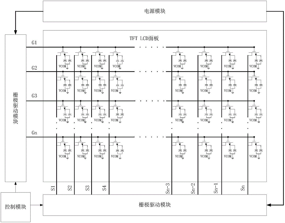
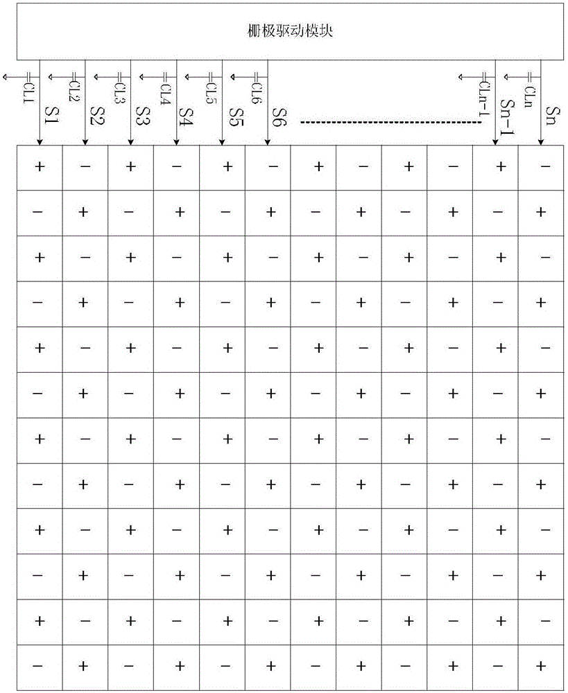
The advantages of frame inversion, row inversion and column inversion are low power consumption, but the disadvantage is that the display effect is not good, and cross-talk is prone to occur; in order to obtain the optimal display effect, most of the industry adopts the method of point inversion, But the problem is that because the polarity of each display pixel is different from that of the surrounding pixels, the power consumption of dot flipping is the largest power consumption among these flipping methods.
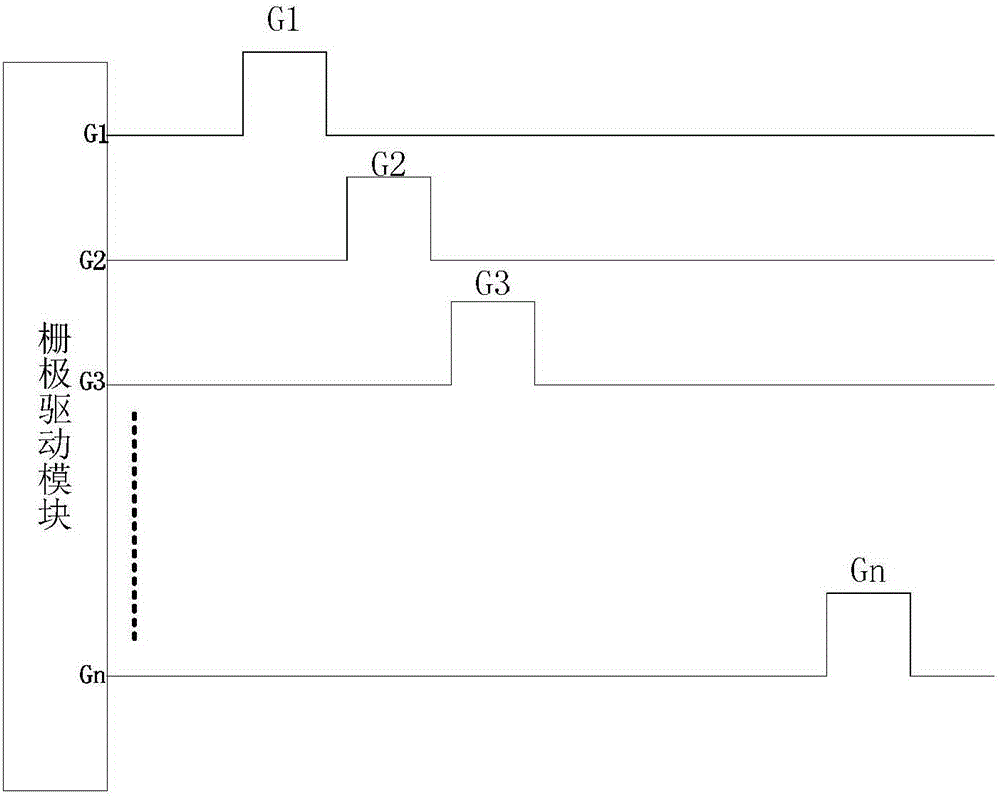
Gate drive and source drive waveforms such as Figure 4 As shown, it can be seen that in this case, when driving the first row and the second row, the polarity of the column needs to be reversed once, so that the parasitic capacitance CLn corresponding to the column driving module needs to complete a polarity change , that is, from positive polarity to negative polarity or from negative polarity to positive polarity, due to the large range of voltage changes, a lot of power consumption will be consumed

Method used


Image

  • Liquid crystal display drive method and circuit
  • Liquid crystal display drive method and circuit
  • Liquid crystal display drive method and circuit

Examples


Embodiment Construction

[0018] It should be noted that, in the case of no conflict, the embodiments in the present application and the features in the embodiments can be combined with each other.

[0019] A method for driving a liquid crystal display with low power consumption, the method comprising: taking one frame as the minimum period, first sequentially turning on the gate drive scanning lines of each odd-numbered row, and each source drive scan line charges the corresponding pixel module ; After the pixel modules in odd rows are fully charged, turn on the gate drive scan lines of each even row in turn, and each source drive scan line charges the corresponding pixel modules.

[0020] As a further preferred embodiment, when the row is switched between rows, the polarity of the source driver module will not be reversed, and the charge on the parasitic capacitance of the wiring will not be switched between positive and negative, which can effectively reduce the power consumption. consumption.

[0...


PUM


Abstract

The invention discloses a liquid crystal display drive method and circuit. The method comprises the following steps: a frame is taken as a minimum period, gate electrode drive scanning lines in various odd rows are successively conducted firstly, and various source electrode drive scanning lines charge corresponding pixel modules; and, after charging of the odd-row pixel modules is finished, gate electrode drive scanning lines in various even rows are successively conducted, and the various source electrode drive scanning lines charge corresponding pixel modules. The liquid crystal display drive circuit comprises a gate electrode drive module, a source electrode drive module and a control module; and the gate electrode drive module is used to apply signals to the gate electrode drive scanning lines, and the source electrode drive module is used to apply signals to the source electrode drive scanning lines. Consumption is equal to power consumption of column overturn, and a point overturn reality effect is achieved at the same time; and the best picture quality is guaranteed, and power consumption is effectively reduced at the same time. The liquid crystal display drive method and circuit can be widely applied to the field of a display device.

Description

technical field [0001] The invention relates to the field of display devices, in particular to a liquid crystal display driving method and circuit. Background technique [0002] Display is the most important way of human-computer interaction. TFTLCD has become the most important material in today's display because of its excellent display effect, mature industrial chain, and low price. Divided by driving mode, TFTLCD liquid crystal drive is divided into frame inversion mode, row inversion mode, column inversion mode, and dot inversion mode. The advantages of frame inversion, row inversion and column inversion are low power consumption, but the disadvantage is that the display effect is not good, and cross-talk is prone to occur; in order to obtain the optimal display effect, most of the industry adopts the method of point inversion, But there is a problem that, since the polarity of each display pixel is different from that of the surrounding pixels, the power consumption o...

Claims


Application Information

Patent Timeline
IPC IPC(8): G09G3/36
CPCG09G3/3614G09G3/3648
Inventor 王富中汤守志邓华
Owner SHENZHEN XINYI PHOTOELECTRIC CO LTD
Learn More