Motor and method of manufacturing the same

A technology of motors and bus bars, which is applied in the field of motor and motor manufacturing, and can solve the problems of increasing the number of parts and increasing manufacturing costs

Active Publication Date: 2016-07-06
NIDEC CORP
View PDF9 Cites 45 Cited by
  • Summary
  • Abstract
  • Description
  • Claims
  • Application Information

AI Technical Summary

Problems solved by technology

[0005] There is a problem that the connection conductors described in Japanese Patent No. 3650372 are arranged in such a way that the respective connection conductors formed by bending the lead wires are arranged in the grooves of the connection conductor holder so that the coil connection terminals face outward in the radial direction. In order to weld the part where the two lead wires are arranged and the lead wires are not expanded, the connecting conductor holder that becomes deeper in the radial direction requires a welding process in the manufacturing method, which increases the manufacturing cost
[0006] In addition, since the terminal coil described in Japanese Laid-Open Patent No. 2010-11690 is easy to form the terminal coil, two linear conductors are required for one terminal part, so the number of parts increases and the problem of high manufacturing cost arises.

Method used


Image

  • Motor and method of manufacturing the same
  • Motor and method of manufacturing the same
  • Motor and method of manufacturing the same

Examples


Deformed example 1

[0154] later according to Figure 15 The neutral point bus bar 240 and the bus bar holder 160 in Modification 1 that can be adopted in the motor 1 of the present embodiment will be described.

[0155] Figure 15 It is a plan view showing a part of the neutral point bus bar 240 and the bus bar holder 160 included in the motor 1 . The main difference between the neutral point bus bar 240 of Modification 1 and the above-mentioned embodiment is the opening direction of the coil end connecting portion 242 . Furthermore, the main difference between the bus bar holder 160 of Modification 1 and the above-mentioned embodiment is that the notch 164 is provided. In addition, the same code|symbol is attached|subjected to the same structural member as 1st Embodiment mentioned above, and description is abbreviate|omitted.

[0156] The neutral point bus bar 240 has two main body parts 241 and three coil end connection parts 242 . Two main body parts 241 and three coil end connecting part...

Deformed example 2

[0167] Afterwards, according to Figure 16 The bus bar holder 260 of Modification 2 that can be employed in the motor 1 of the present embodiment will be described.

[0168] Figure 16 It is a plan view showing a part of the neutral point bus bar 240 and the bus bar holder 260 included in the motor 1 . Compared with the neutral point bus bar 40 of the above-mentioned embodiment, the main difference is the opening direction of the coil end connection portion 242 . Furthermore, the main difference is that the bus bar holder 260 of Modification 1 is provided with the through-hole 264 .

[0169] In addition, the same code|symbol is attached|subjected to the same structural member as the above-mentioned modification 1, and description is abbreviate|omitted.

[0170] The bus bar holder 260 has a circular plate shape provided with an opening 269 . The opening 269 passes through in the axial direction.

[0171] Bus bar holder 260 is arranged on the front side (-Z side) of neutral...


PUM


Abstract

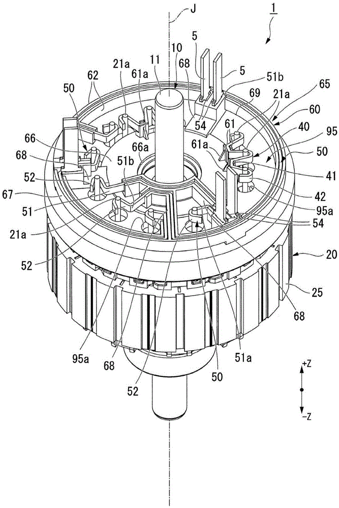
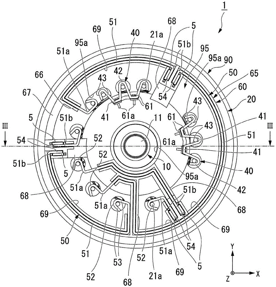
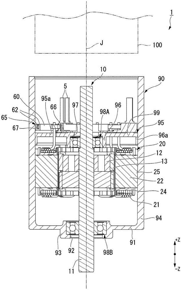
The invention relates to a motor and a method of manufacturing the same. The motor includes a rotor having a shaft which has its center on a center axis extending in one direction; a stator which surrounds the rotor in the axial circumference, and includes a plurality of coils; and bus bars connecting coil ends extending from the coils. The bus bars may include a plate shape member bent in a thickness direction, a width direction of the bus bars being identical to an axial direction of the motor. Each of the bus bars may include a main body portion, and a coil end connection portion which extends from the main body portion and grips one of the coil ends at an opening that is open toward one direction within a plane perpendicular to the axial direction.

Description

technical field [0001] The present invention relates to a motor and a method of manufacturing the motor. Background technique [0002] There is known a motor having bus bars for wiring the coil ends at any position. [0003] Japanese Patent No. 3650372 describes a connecting conductor having a coil connection terminal portion formed by bending a lead wire. The coil connection terminal portion of the connecting conductor is a linear wire that protrudes outward and is folded back, and the folded and returned linear wires are welded to each other. [0004] Japanese Laid-Open Patent Publication No. 2010-11690 describes a splice coil in which two linear conductors are overlapped. The connecting coil has a connecting portion connected to the winding end of the stator coil, and the connecting portion is formed by bending two linear conductors to be connected while sandwiching the winding end. [0005] There is a problem that the connection conductors described in Japanese Patent...

Claims


Application Information

Patent Timeline
Patent Type & Authority Applications(China)
IPC IPC(8): H02K13/00H02K3/50H02K15/00
CPCH02K3/50H02K13/00H02K15/00H02K3/522H02K2203/09H02K15/0068H02K3/28H02K3/38
Inventor 三分一浩司小川幸祐服部隆志
Owner NIDEC CORP
Why Eureka
Try Eureka