Transport system and transport method

A technology of conveying device and conveying path, which is applied in the direction of transmission device, packaging, material inspection products, etc., which can solve the problems of device structure and maintenance operation complexity, etc., and achieve the effect of lightened inspection work, less number of parts and excellent maintainability

Inactive Publication Date: 2013-09-18
AOI SEIKI
View PDF7 Cites 24 Cited by
  • Summary
  • Abstract
  • Description
  • Claims
  • Application Information

AI Technical Summary

Problems solved by technology

[0003] In the above-mentioned belt-driven conveying device, the device structure and maintenance work are complicated, and a conveying device with a simple structure and good maintainability is desired.

Method used


Image

  • Transport system and transport method
  • Transport system and transport method
  • Transport system and transport method

Examples


no. 1 Embodiment approach

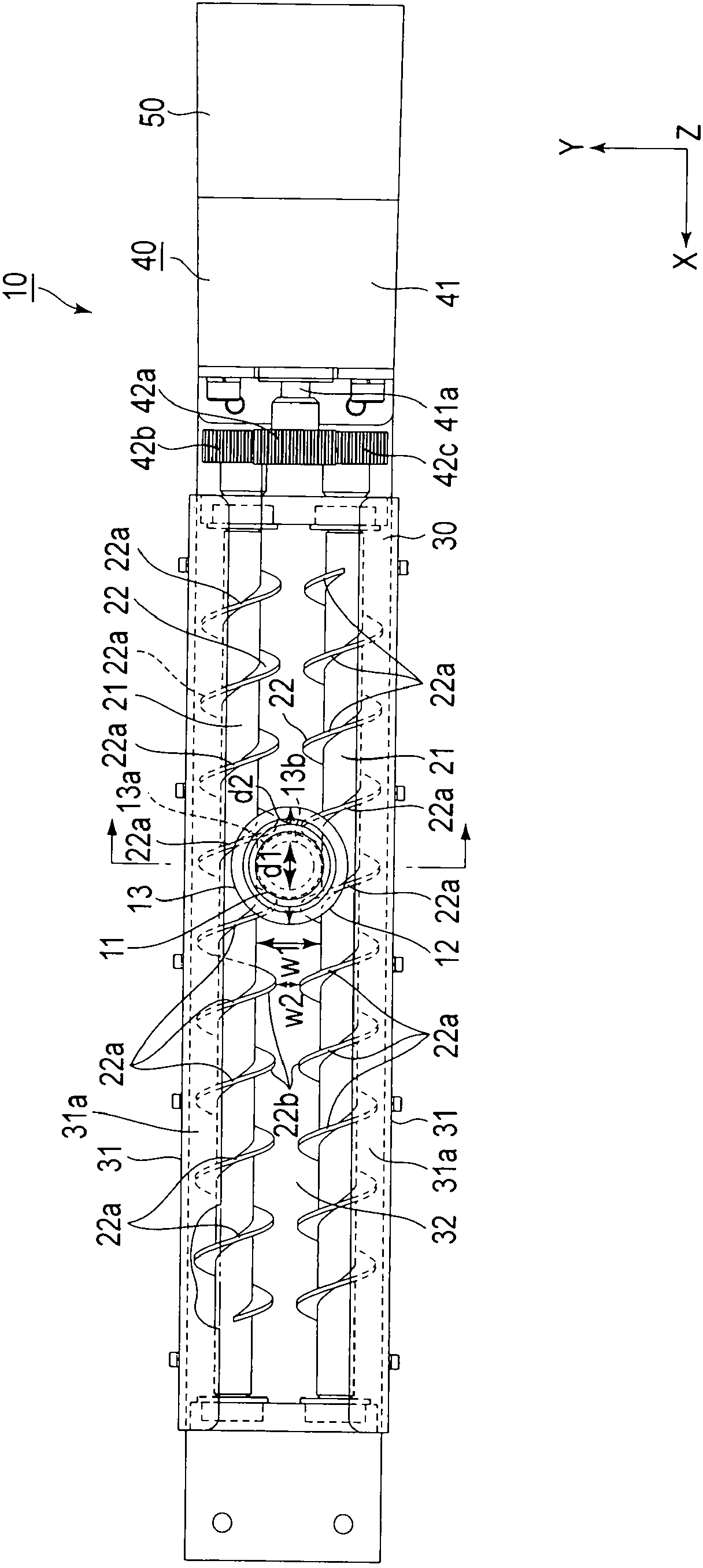
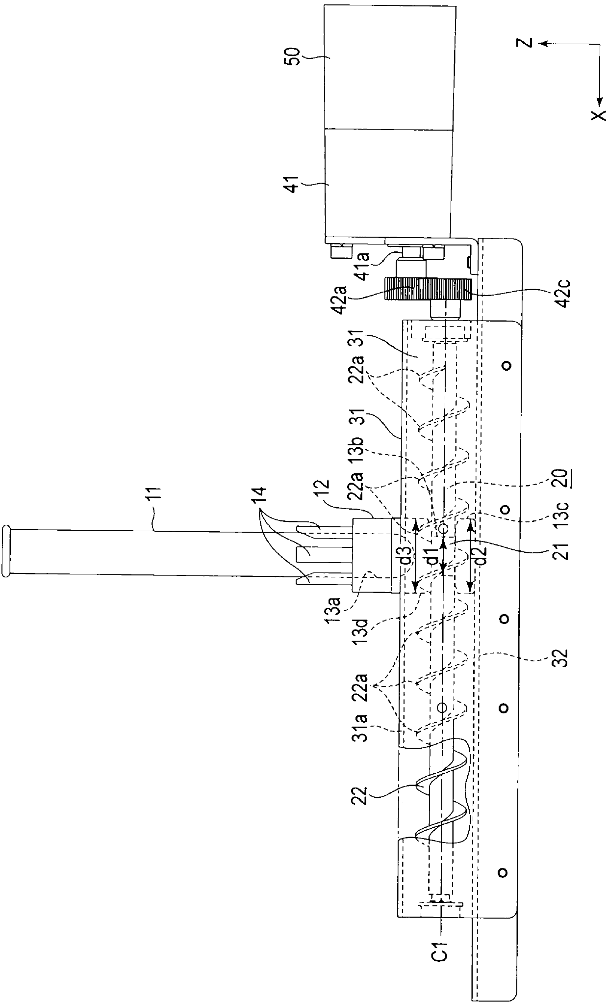
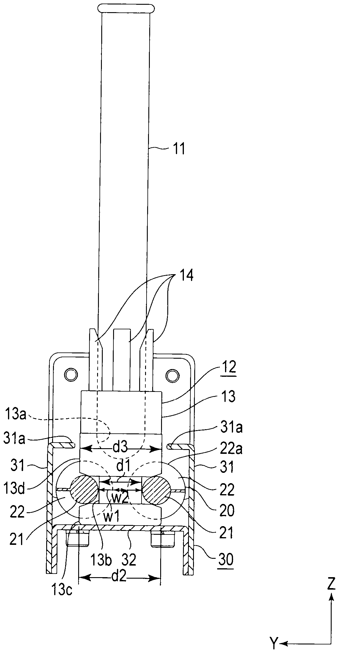
[0017] Next, the transport device 10 according to the first embodiment of the present invention will be described. figure 1 is a plan view of the transport device 10 of the present embodiment, figure 2 is a side view of the delivery device 10, image 3 is a cross-sectional view of the conveying device 10 . In addition, in each figure, the structure is enlarged, reduced, and abbreviated and shown appropriately for description. Arrows X, Y, and Z in the figure indicate three directions perpendicular to each other.

[0018] The transport device 10 has a function of transporting a holding member 12 holding a test tube 11 as a sample container containing a sample such as blood from one end side to the other end side in the transport direction along the arrow X.

[0019] The conveying device 10 includes: a lead screw 20 arranged along a predetermined conveying path; a frame 30 having a pair of guide rails 31 arranged on both sides of the lead screw 20 with a certain width; a dri...

no. 2 Embodiment approach

[0039] Next, a transport device 100 according to a second embodiment of the present invention will be described. Figure 4 is a plan view of the transport device 100 of the present embodiment, Figure 5 is a side view of the delivery device 100, Figure 6 is a cross-sectional view of the conveying device 100 . In addition, in each figure, the structure is enlarged, reduced, and abbreviated and shown appropriately for description. Arrows X, Y, and Z in the figure indicate three directions perpendicular to each other.

[0040] The conveying device 100 of the present embodiment includes: a lead screw 20 arranged so as to extend over a predetermined conveying path; a frame 30 having a pair of guide rails 31 set to a certain width supporting both sides of the lead screw 20 ; and a driving part. 40 , which drives the lead screw 20 to rotate; the control unit 50 , which controls the operation of the driving unit 40 .

[0041] In addition, in this embodiment, the point of differen...


PUM


Abstract

According to an embodiment, a transport system configured to transport a receptacle which accommodates an upright sample holder containing a sample, characterized by comprising, a screw comprising a rotatable shaft disposed along a predetermined transport path and a helical ridge protruding outward from an outer peripheral surface of the shaft, and a drive unit configured to rotate the screw. The transport method according to another shape utilizes a pair of parallel screws for conveying the receptacle, and conveys the receptacle which is held among a plurality of ridges which are arranged in an axial direction in a transportation path. The transport system and transport method of the invention have the following advantages: small number of components, simplified device structure, and reduced manufacturing cost.

Description

technical field [0001] The present invention relates to a conveying device and a conveying method, and relates to conveying a holding member of a sample container. Background technique [0002] As a conveying device for conveying specimen containers capable of accommodating specimens such as blood, a conveyer-driven conveying device comprising the following parts is known: a conveying belt stretched on a base along the conveying direction; and a rotating roller disposed on the conveying belt. The opposite side of the conveyor belt; a conveying mechanism such as a motor, which drives the rotating roller to rotate to convey the conveyor belt; a pair of guide rails, which are arranged on the upper part of the conveyor belt with a certain width (for example, Japanese Patent Application Laid-Open No. 2005-263478). In such a conveyor-driven transport device, a holding member holding a sample container is placed on a conveyor belt, the holding member is engaged with a guide rail to...

Claims


Application Information

Patent Timeline
Patent Type & Authority Applications(China)
IPC IPC(8): B65G33/04B65G33/06B65G33/24
CPCG01N35/04G01N2035/0406G01N2035/0487F16H25/20G01N33/49G01N35/10B65G33/06
Inventor 伊藤照明
Owner AOI SEIKI
Why Eureka
Try Eureka