Biological information measuring module, biological information measuring apparatus, light detecting apparatus, light detecting module, and electronic apparatus

a biological information and measuring module technology, applied in the direction of telemetry patient monitoring, diagnostic recording/measuring, catheter, etc., can solve the problems of deteriorating throughput and cost of manufacturing process, difficulty in reducing noise components, erosion caused,

Inactive Publication Date: 2016-07-14
SEIKO EPSON CORP
View PDF8 Cites 25 Cited by
  • Summary
  • Abstract
  • Description
  • Claims
  • Application Information

AI Technical Summary

Benefits of technology

[0011]An advantage of some aspects of the invention is to solve at least a part of the problems...

Problems solved by technology

In the light detecting apparatus, there is a concern for a problem caused by a measurement environment such as the erosion of the apparatus which is caused by moisture existing in the measurement environment.
In addition, in a type of light detecting apparatus worn on a body, there is also a concern for erosion caused by sweat, and the like.
However, in a biological information measuring module and a biological information measuring apparatus using the biological information measuring module disclosed in Pamphlet of International Publication No. 2014/091424A2, a wearing state varies due to on exercise or body motion of a wearer (test subject) who is a user, and thus a gap may be generated between a light receiving element and a skin surface, which results in a difficulty in reducing noise components.
In addition, in the inventions disclosed in ...

Method used


Image

  • Biological information measuring module, biological information measuring apparatus, light detecting apparatus, light detecting module, and electronic apparatus
  • Biological information measuring module, biological information measuring apparatus, light detecting apparatus, light detecting module, and electronic apparatus
  • Biological information measuring module, biological information measuring apparatus, light detecting apparatus, light detecting module, and electronic apparatus

Examples


first embodiment

1. Overall Configuration Example of Biological Information Measuring Apparatus

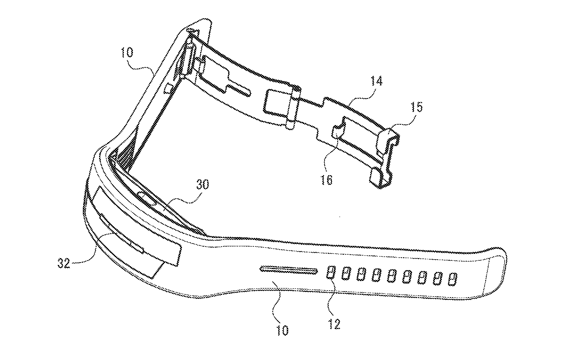
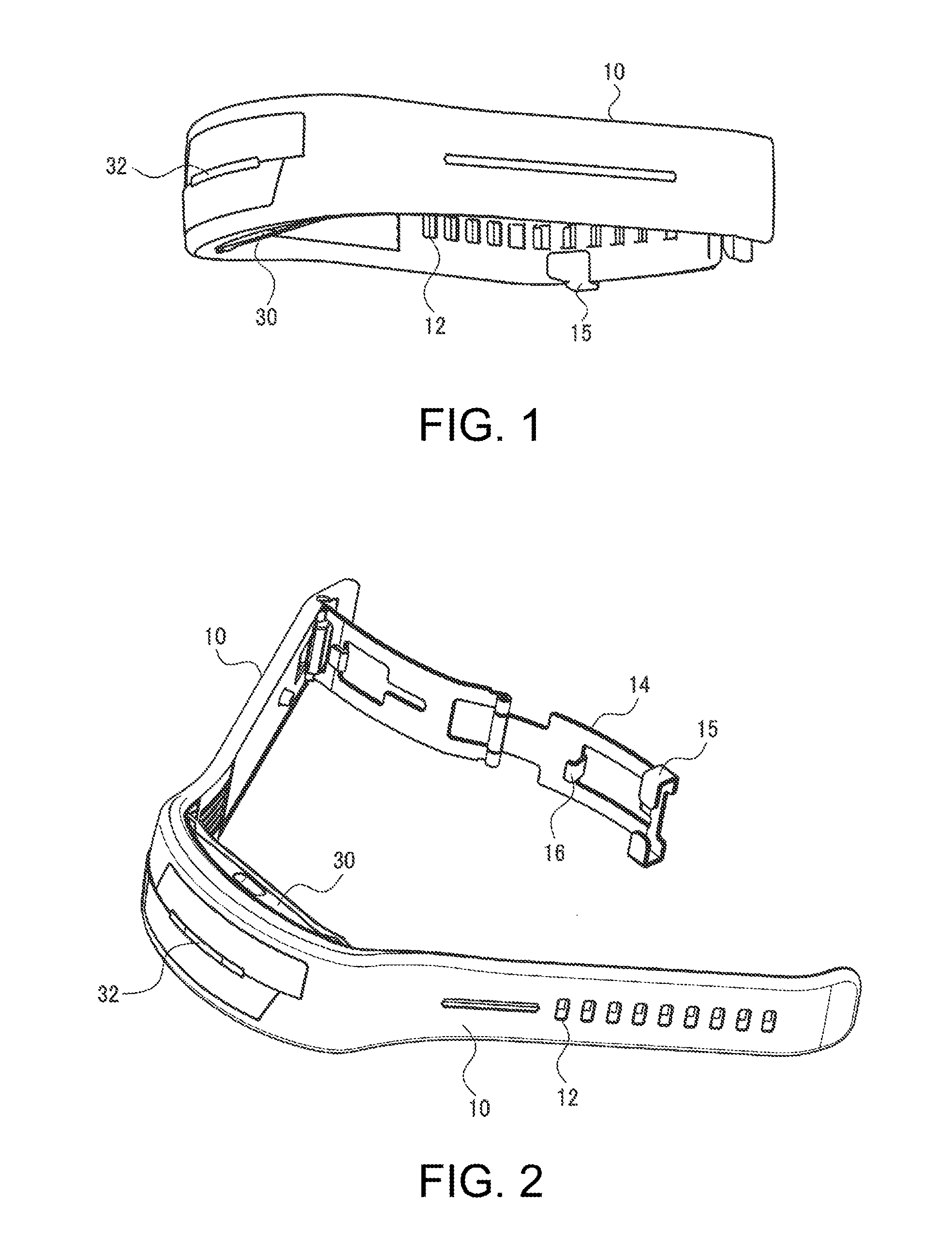
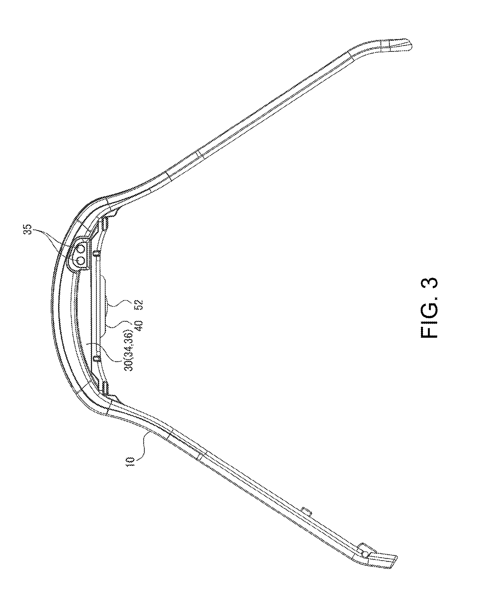
[0111]FIGS. 1 to 3 are schematic diagrams illustrating the exterior of a biological information measuring apparatus (biological information detecting apparatus) according to a first embodiment. FIG. 1 is a diagram when the biological information measuring apparatus is seen from the front, FIG. 2 is a diagram when the biological information measuring apparatus of FIG. 1 is obliquely seen from above, and FIG. 3 is a diagram when the biological information measuring apparatus is seen from the side.

[0112]As illustrated in FIGS. 1 to 3, the biological information measuring apparatus of this embodiment includes a band portion 10, a case portion 30, and a sensor unit 40 as a biological information measuring module. The case portion 30 is attached to the band portion 10. The sensor unit 40 is provided in the case portion 30. In addition, the biological information measuring apparatus includes a processing unit 200...

configuration example 1

of Sensor Unit

[0134]First, Configuration Example 1 of the sensor unit 40 will be described with reference to FIGS. 6 to 9. The sensor unit 40 of Configuration Example 1 includes a light receiving unit 140, a light emitting unit 150, and a wall portion 70 as a frame which is provided between the light receiving unit 140 and the light emitting unit 150. The light receiving unit 140 and the light emitting unit 150 are lined up at a predetermined interval, and are mounted on a supporting surface 160a of a substrate 160 (sensor substrate) as a supporting unit. The light emitting unit 150 emits light to an object (test subject or the like). The light receiving unit 140 receives light (reflected light, transmitted light, or the like) via the object. For example, when the light emitting unit 150 emits light and the light is reflected by an object (for example, a blood vessel), the light receiving unit 140 receives and detects the reflected light. The light receiving unit 140 can be realized...

example 1

[0167]As described above, the above-mentioned light receiving unit 140 in the sensor unit 40 can be configured as a light detecting apparatus capable of contributing to the realization of highly-accurate measurement of biological information in a biological information measuring apparatus. Hereinafter, an example of a light detecting apparatus will be described. Meanwhile, the example to be described below does not wrongly limit the contents of the invention described in the appended claims. In addition, the entire configuration described in this example is not necessarily an essential element of the invention.

[0168]The light detecting apparatus has a problem that the securing of moisture resistance and the securing of light transmittance are contrary to each other. For example, when moisture resistance is secured by simply protecting the light detecting apparatus by a silicon nitride film, light transmittance deteriorates.

[0169]Consequently, in this example, the entirety of a semic...


PUM


Abstract

A biological information measuring module includes a light emitting unit that emits light, a light receiving unit that receives the light via an object, and a multilayered film optical filter that is provided on the light receiving unit on a side where the light is incident. The multilayered film optical filter is constituted by a laminated body of five or more layers and 120 or less layers.

Description

CROSS-REFERENCES TO RELATED APPLICATIONS[0001]This application claims priority to Japanese Patent Applications No. 2015-003905, filed Jan. 13, 2015, and No. 2015-045582, filed Mar. 9, 2015, all of which are hereby incorporated by reference.BACKGROUND[0002]1. Technical Field[0003]The present invention relates to a biological information measuring module, and a biological information measuring apparatus, a light detecting apparatus, a light detecting module, and an electronic apparatus which include the biological information measuring module.[0004]2. Related Art[0005]Hitherto, there have been known measuring modules that are worn around body parts, such as a wrist, by a band or the like and measure biological information such as a wearer's pulse waves, and wristwatch type wrist devices having a function of measuring the biological information. For example, Pamphlet of International Publication No. 2014 / 091424A2 discloses a biological information measuring apparatus which is worn arou...

Claims


Application Information

Patent Timeline
IPC IPC(8): A61B5/024H01L31/0216H01L31/02A61B5/026
CPCA61B5/02444A61B5/02438H01L31/02005H01L31/02162A61B5/0261A61B5/0002A61B5/02427A61B5/4806A61B5/681A61B2562/0233G16H40/63G16H40/67H01L31/1037
Inventor UEMATSU, AKIRAINAGAKI, AKIRAMATSUO, ATSUSHIHASEI, HIRONORI
Owner SEIKO EPSON CORP
Why Eureka
Try Eureka