Supercharge Your Innovation With Domain-Expert AI Agents!

Power Conversion Device And Control Method Thereof

A technology of power conversion device and control mechanism, which is applied in high-efficiency power electronic conversion, output power conversion device, conversion of AC power input to DC power output, etc., can solve problems such as large losses, reduce switching losses, eliminate specific high The effect of subharmonic components

Active Publication Date: 2016-07-06
KK TOSHIBA
View PDF9 Cites 0 Cited by
  • Summary
  • Abstract
  • Description
  • Claims
  • Application Information

AI Technical Summary

Problems solved by technology

However, when the power conversion device is used with a large amount of power, the loss caused by switching the switching element becomes larger

Method used


Image

  • Power Conversion Device And Control Method Thereof
  • Power Conversion Device And Control Method Thereof
  • Power Conversion Device And Control Method Thereof

Examples


Embodiment Construction

[0017] Hereinafter, embodiment will be described using drawings.

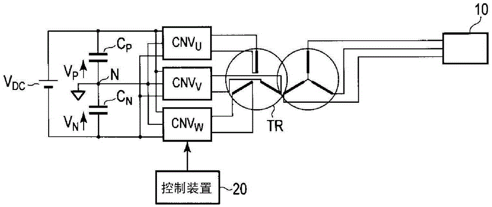
[0018] figure 1 It is a diagram showing an example of the circuit configuration of the power conversion device in the embodiment. This power conversion device converts a DC voltage into an arbitrary frequency and voltage to drive a three-phase (UVW phase) AC load 10 .

[0019] U-phase power converter unit CNV U Input DC voltage V DC . The power conversion device unit CNV U The output terminal of is connected to the U-phase primary side winding of the converter TR.

[0020] V-phase, W-phase power converter unit CNV V 、CNV W Also input the DC voltage V common to the U phase DC The output terminals of these power conversion device units are connected to the V-phase and W-phase primary-side windings of the converter TR one-to-one.

[0021] figure 1 The control device 20 of the shown power conversion device unit outputs a gate instruction (gate instruction) to the switching elements constituting the power ...


PUM


Abstract

According to one embodiment, there is provided a power conversion device, including a control unit (20) configured to control ON / OFF of a switching element of a neutral-point-clamped power conversion device unit, wherein the control unit (20) drives the power conversion device unit by a one-pulse control, controls a phase difference of an output voltage of the power conversion device unit with respect to a reference phase of to control an active current component of an output current of the power conversion device unit, and controls ON / OFF based on: (a) a phase angle for eliminating a predetermined odd-order harmonic component of the output voltage; and (b) a sum of the reference phase and the phase difference.

Description

technical field [0001] Embodiments of the present invention relate to a power conversion device and a control method thereof. Background technique [0002] A power conversion device that outputs large power converts high voltage. Therefore, it is necessary to increase the withstand voltage by using switching elements with high withstand voltage or connecting switching elements with low withstand voltage in series. Furthermore, it is necessary to increase the output voltage by multiplying the power conversion device by using a transformer. [0003] When the withstand voltage of the switching element is high, the switching loss of the switching element is large. Therefore, control is sometimes performed to cancel specific harmonics by switching the switching element on and off only once (one pulse) per one cycle of the output frequency to deviate the phase. This monopulse control for canceling specific harmonics has the advantage of being able to reduce losses due to switch...

Claims


Application Information

Patent Timeline
IPC IPC(8): H02M7/487H02M1/12
CPCH02M1/12H02M7/487H02M1/0038H02M1/0054Y02B70/10
Inventor 长谷川隆太河野真也藤田崇石月照之
Owner KK TOSHIBA
Features
  • R&D
  • Intellectual Property
  • Life Sciences
  • Materials
  • Tech Scout
  • Unparalleled Data Quality
  • Higher Quality Content
  • 60% Fewer Hallucinations
Learn More