Bone-conduction speaker

A technology of bone conduction speakers and vibrators, applied in the direction of bone conduction transducers, hearing devices, sensors, sensor types, etc.

Active Publication Date: 2016-07-06
唐迎
View PDF7 Cites 8 Cited by
  • Summary
  • Abstract
  • Description
  • Claims
  • Application Information

AI Technical Summary

Problems solved by technology

[0007] The bone conduction loudspeaker according to the present invention aims to solve the previously described problems, which bone conduction loudspeaker comprises:

Method used


Image

  • Bone-conduction speaker
  • Bone-conduction speaker
  • Bone-conduction speaker

Examples


no. 1 approach

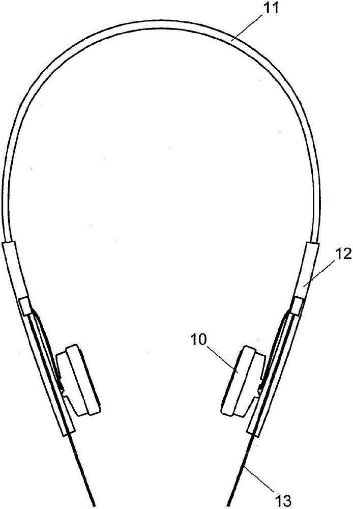
[0028] Reference below figure 1 , Figure 2A and Figure 2B An embodiment is described in which the bone conduction speaker according to the present invention is applied to a bone conduction earphone.

[0029] The bone conduction earphone of the present embodiment includes a U-shaped support (headband) 11; a speaker attachment portion 12 provided at each end of the support 11; a bone conduction speaker 10 attached to the speaker attachment portion each of 12; and other elements.

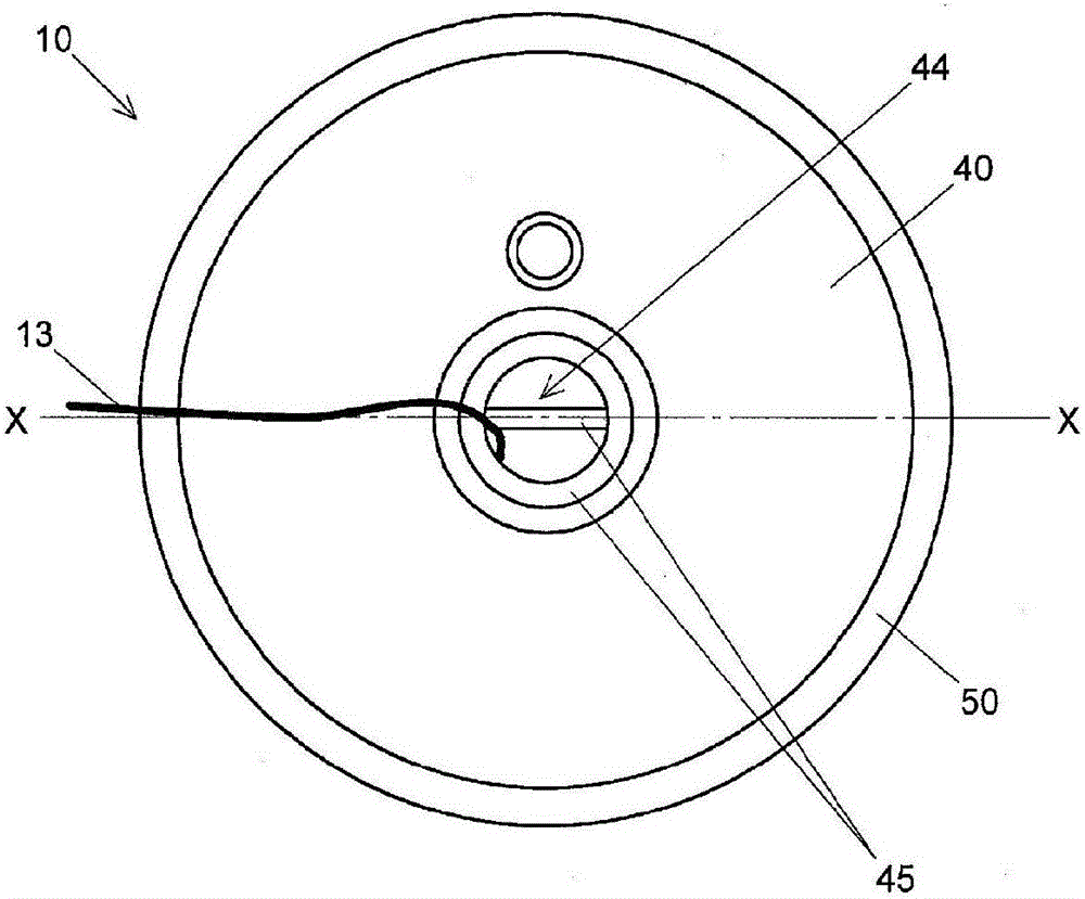
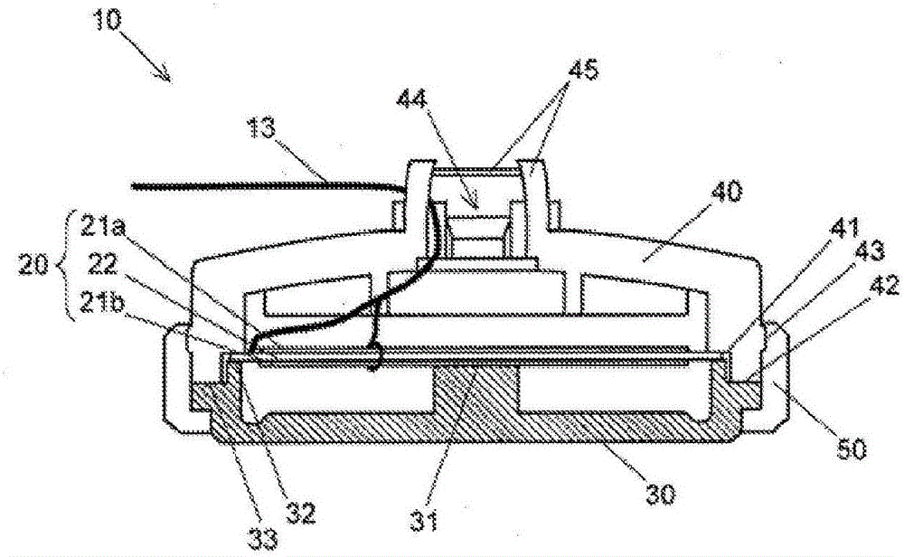
[0030] The bone conduction speaker 10 includes a disk-shaped piezoelectric vibrating element 20 , a vibrator 30 , a back case 40 , a side cover 50 , two cables 13 , and other components, and the vibrator 30 is connected to one side of the piezoelectric vibrating element 20 . and conduct the vibration of the element 20 to an external object (such as a skull), the back case 40 is arranged on the other side of the piezoelectric vibrating element 20, and the side cover 50 is used to connect the vibrat...

no. 2 approach

[0052] Image 6 is a schematic side view of the second embodiment, in which the bone conduction speaker according to the present invention is applied to an in-ear bone conduction earphone.

[0053] The bone conduction speaker 90 used in the present in-ear bone conduction earphone has a solid earplug portion 93 at the center on the side of the vibrator 92 opposite to the piezoelectric vibrating element. Other components are the same as those used in the bone conduction speaker 10 of the first embodiment.

[0054] With the in-ear bone conduction earphone of this embodiment, the vibration of the vibrator 92 is transmitted to the cartilage or bone near the external auditory canal through the earplug part 93 . Since the earplug part 93 is solid, the loss of vibration energy is smaller than in the case of a hollow earplug part. Therefore, vibration can be efficiently transmitted from the piezoelectric vibration element to the user.


PUM


Abstract

The bone-conduction speaker includes a plate-shaped piezoelectric vibration element (20) which has its circumferential portion fixed to a circumferential edge projection (32) of a vibrator (30) on one side, while its center is in contact with a central projection (31) of the vibrator (30). The other side of the element (20) is covered with a resin-made back case (40). The central projection (31) is in contact with the center of the piezoelectric vibration element (20), where the vibration generated by a conversion of sound signals has the largest amplitude. Through this contact, the vibrator (30) can efficiently pick up vibrations. Since no vibration damper is used, the vibration is conducted efficiently and with no absorption. The resin-made back case (40) absorbs air vibration generated in a space between the piezoelectric vibration element (20) and the back case (40), whereby the leakage of sound to the outside is suppressed and the acoustic feedback is reduced.

Description

[0001] This application claims priority to Japanese Patent Application No. 2013-268751, filed with the Japan Patent Office on Dec. 26, 2013, entitled "BONE-CONDUCTION SPEAKER (bone conduction speaker)", the entire contents of which are hereby incorporated by reference incorporated. technical field [0002] The present invention relates to a bone conduction speaker for converting a sound signal into vibration through a piezoelectric element and transmitting the vibration to an auditory nerve through a skull without passing through an eardrum. Background technique [0003] In recent years, piezoelectric speakers have been widely used in bone conduction speaker systems instead of conventionally used coil speakers. Piezoelectric speakers consume less power and generate a smaller amount of electromagnetic waves. [0004] Patent Document 1 discloses an in-ear bone conduction speaker (earphone) having an annular damper attached to the circumference of a disc-shaped piezoelectric e...

Claims


Application Information

Patent Timeline
Patent Type & Authority Applications(China)
IPC IPC(8): H04R1/10
CPCH04R1/1016H04R1/288H04R5/033H04R17/00H04R2460/13
Inventor 唐迎大野博乡堀井尚
Owner 唐迎
Why Eureka
Try Eureka