
Improved inner-pushing type clamping device for numerical control tube bending machine

A clamping device and an improved technology are applied in the field of an improved internal push-type clamping device for a numerically controlled pipe bender, which can solve the problems of poor rotary sealing of an oil cylinder, easy oil leakage, short service life, etc., so as to increase the convenience The effect of reducing the difficulty of sealing and reducing the production cost

Active Publication Date: 2016-07-13
ANHUI DEXI DHI TECH
View PDF11 Cites 12 Cited by
  • Summary
  • Abstract
  • Description
  • Claims
  • Application Information

AI Technical Summary

Problems solved by technology

[0005] Aiming at the problem that the oil cylinder of the clamping device used for the CNC pipe bending machine is not good enough to easily cause oil leakage and the service life is short when the oil cylinder of the existing clamping device for the CNC pipe bending machine rotates, the present invention provides an improved internal push-type clamping device for the CNC pipe bending machine. The improvement of the structure can avoid the problem of oil leakage due to poor rotary seal of the oil cylinder, thereby improving the working stability of the clamping device and prolonging the service life

Method used


Image

  • Improved inner-pushing type clamping device for numerical control tube bending machine
  • Improved inner-pushing type clamping device for numerical control tube bending machine
  • Improved inner-pushing type clamping device for numerical control tube bending machine

Examples


Embodiment 1

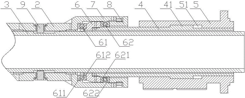
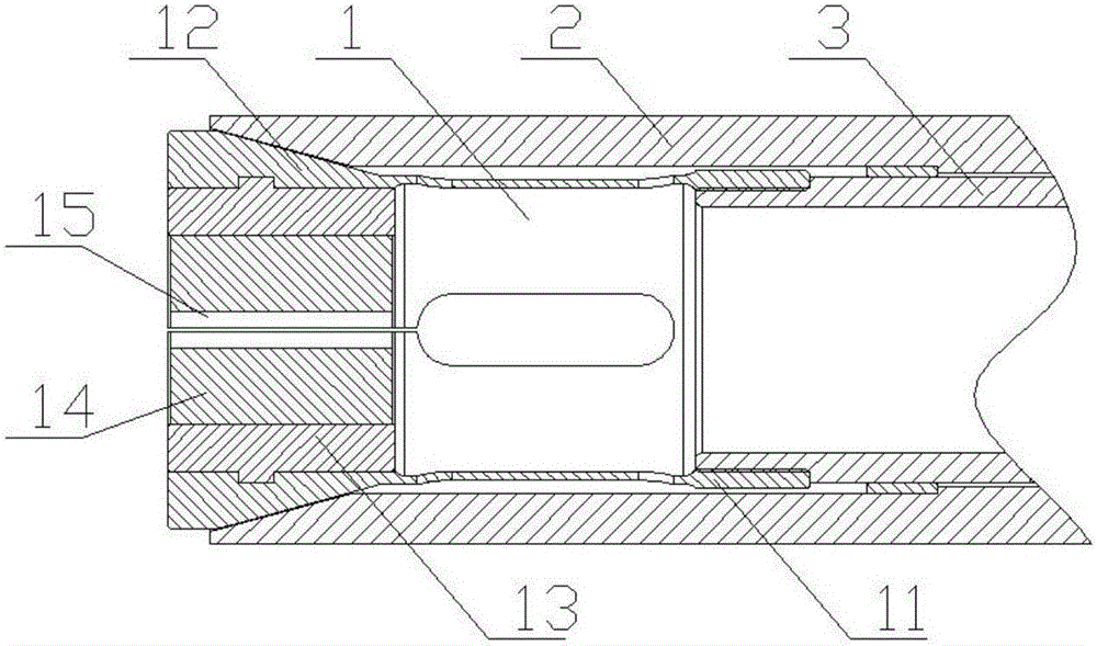
[0038] Such as image 3 As shown, an improved internal push-type clamping device for a CNC pipe bender includes a collet 1, an oil cylinder, and parts connecting the collet 1 and the cylinder, and the parts connecting the collet 1 and the cylinder include a push collet 2 and the rotating rod 3;

[0039] Such as figure 2 As shown, the oil cylinder includes a cylinder body 5 and a piston rod 4 arranged in the cylinder body 5. The push jacket 2 is arranged on the extended end of the piston rod 4. The push jacket 2 and the piston rod 4 are relatively fixed in the axial direction, and can be relatively fixed around the axis. Rotate, specifically, the extended end of the piston rod 4 is provided with a piston rod push clamp connecting seat 6; the connection between the push jacket 2 and the extended end of the piston rod 4 is provided with a rotating connecting sleeve 7 and a supporting sleeve 8; the rotating connecting sleeve 7 is set On the piston rod push clamp connection seat 6...


PUM


Abstract

The invention discloses an improved inner-pushing type clamping device for a numerical control tube bending machine and belongs to the field of numerical control tube bending machines. The improved inner-pushing type clamping device solves the problems that an oil cylinder of an existing clamping device for a numerical control tube bending machine is poor in rotation sealing in the autorotation process and is likely to leak oil, and the service life is short. The improved inner-pushing type clamping device comprises a flexible chuck, an oil cylinder and a component, wherein the flexible chuck and the oil cylinder are connected through the component. The component for connecting the flexible chuck and the oil cylinder comprises a chuck pushing bush and a rotating rod. The oil cylinder comprises a cylinder body and a piston rod arranged in the cylinder body, and the chuck pushing bush is arranged at the stretching-out end of the piston rod, is fixed relative to the piston rod in the axial direction and can relatively rotate around the axis. The rotating rod is arranged in the piston rod, and is connected with the chuck pushing bush in the connecting mode that the rotating rod and the chuck pushing bush can rotate synchronous and move relatively in the axial direction. The flexible chuck is arranged at one end of the rotating rod. By means of the improved inner-pushing type clamping device, the problem of oil leakage caused by poor rotation sealing of the oil cylinder can be solved, so that the working stability of the clamping device is improved, and the service life is prolonged.

Description

technical field [0001] The invention belongs to the field of numerically controlled pipe benders, and in particular relates to an improved internal push-type clamping device for numerically controlled pipe benders. Background technique [0002] The CNC pipe bender can perform winding bending of pipes with one bending radius (single mode) or two bending radii (dual mode) in a cold state, and is widely used in bending various pipe fittings and wires in industries such as automobiles and air conditioners. In view of the fact that the clamping device used for CNC pipe bending machines in the past is easy to loosen when the clamping is not tight, the pipe and the clamping device are prone to serious sliding phenomenon and accompanied by damage to the appearance of the pipe, and the clamping is too tight. Tightness is easy to damage the pipe and produce abnormal deformation, and the clamping device itself cannot rotate, resulting in the bent pipe not being absolutely streamlined a...

Claims


Application Information

Patent Timeline
Patent Type & Authority Applications(China)
IPC IPC(8): B21D7/12B21D7/16B21D43/00
CPCB21D7/12B21D7/16B21D43/003
Inventor 吴善普吴善照
Owner ANHUI DEXI DHI TECH
Learn More