
Action method of fully hydraulic autonomous mobile robot arm

An autonomous moving, robotic arm technology, applied in the field of robotic arms, can solve the problems of high labor intensity, serious vulcanization pollution, occupational health hazards of workers, etc., achieve huge market value, improve occupational health of workers, and meet the needs of large-scale mobile operations. Effect

Inactive Publication Date: 2017-10-20
济南鲁智电子科技有限公司
View PDF9 Cites 0 Cited by
  • Summary
  • Abstract
  • Description
  • Claims
  • Application Information

AI Technical Summary

Problems solved by technology

[0003] Mobile robotic arms have huge market potential. Taking the tire manufacturing industry as an example, my country's tire production accounts for about 50% of the world's total. The work still needs to be done manually, and the flexible installation of the green tire to the vulcanizing machine also relies heavily on manual labor. Not only is the labor intensity high, but also the vulcanization pollution in the workshop is serious, which has caused great harm to the occupational health of workers, resulting in a large number of labor shortages in tire companies. Enterprises' demand for mobile robotic arms is about 3,000 units, and the market capacity is about 5 billion yuan; machining (clamping and forging of forgings, clamping and welding of weldments, assembly, selection, and transportation of large-quality parts and components, etc.) Enterprises in industries such as large-scale dangerous goods and ammunition operations, engineering and municipal construction also have a large demand for hydraulically driven mobile robotic arms, with a total market capacity of more than 20 billion yuan

Method used


Image

  • Action method of fully hydraulic autonomous mobile robot arm
  • Action method of fully hydraulic autonomous mobile robot arm
  • Action method of fully hydraulic autonomous mobile robot arm

Examples


Embodiment Construction

[0041] In order to make the technical problems, technical solutions and advantages to be solved by the present invention clearer, the following will describe in detail with reference to the drawings and specific embodiments.

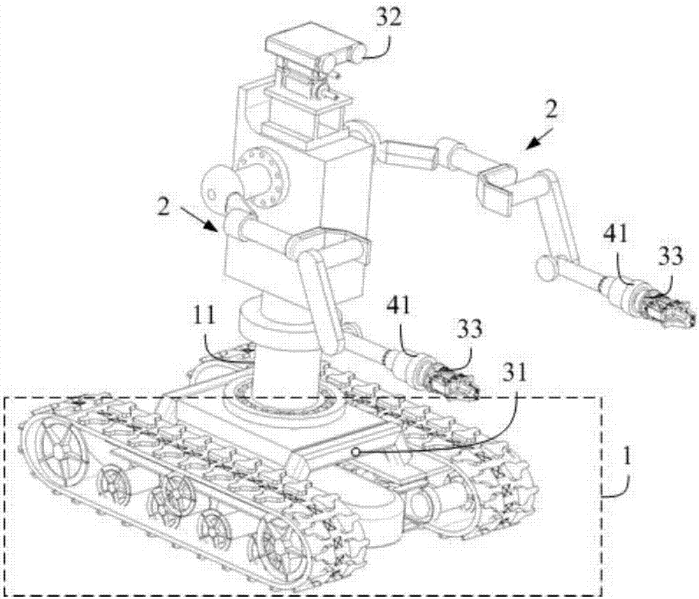
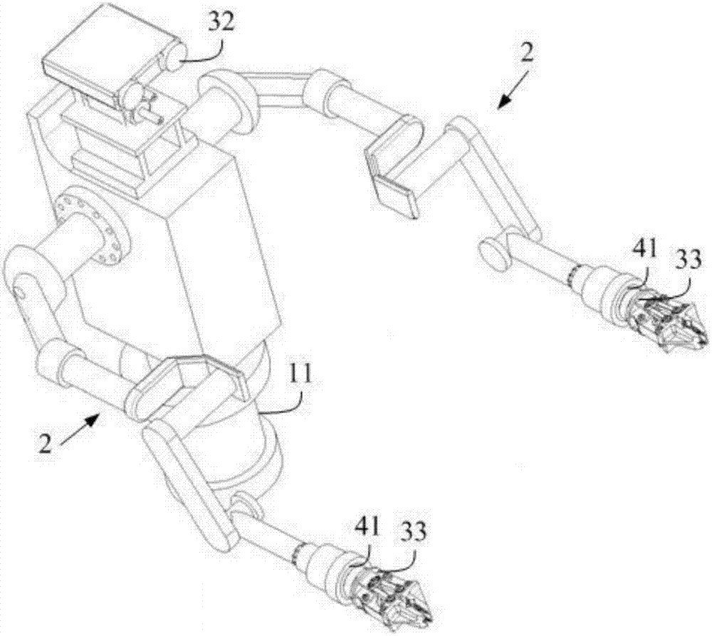
[0042] On the one hand, the present invention provides a kind of fully hydraulic self-moving manipulator, such as Figure 1 to Figure 2 As shown, the omnidirectional mobile platform 1 is included, and the omnidirectional mobile platform 1 is provided with a double robot arm 2, a power system, a visual system, and a perception and control system, wherein:

[0043]The omnidirectional mobile platform 1 is provided with a rotating waist device 11, and the double mechanical arm 2 is arranged on the omnidirectional mobile platform 1 through the rotating waist device 11. The double robotic arm 2 is a humanoid double arm structure with multiple degrees of freedom;

[0044] The power system adopts engine-hydraulic drive mode;

[0045] The visual system includes ...


PUM


Abstract

The invention discloses an action method for a fully hydraulic autonomously moving mechanical arm, which belongs to the technical field of mechanical arms. The fully hydraulic autonomous mobile manipulator includes an omnidirectional mobile platform, which is equipped with dual robotic arms, power system, vision system, and perception and control system. The arm is set on the omni-directional mobile platform through the rotating waist device. The double mechanical arm is a humanoid double arm structure with multiple degrees of freedom; the power system adopts the engine-hydraulic drive mode; the vision system includes a navigation camera, a large field of view servo camera and a hand-eye The camera; the perception and control system includes a joint force sensor, a joint position sensor and a six-dimensional force sensor, and the invention can meet the needs of a large-scale mobile operation of a large-mass workpiece.

Description

technical field [0001] The invention relates to the technical field of mechanical arms, in particular to an action method of a fully hydraulic autonomously moving mechanical arm. Background technique [0002] In the past 30 years, my country's manufacturing industry has achieved rapid development and considerable progress under the advantage of low-cost labor, and has become a world manufacturing power. However, since the second decade of the 21st century, labor costs have risen sharply, and the labor population, mainly those born in the 1980s and 1990s, is less interested in engaging in monotonous and repetitive industrial jobs with poor working conditions. The manufacturing industry uses robots to replace human labor. demands are constantly motivating. [0003] Mobile robotic arms have huge market potential. Taking the tire manufacturing industry as an example, my country's tire production accounts for about 50% of the world's total. The work still needs to be done manual...

Claims


Application Information

Patent Timeline
Patent Type & Authority Patents(China)
IPC IPC(8): B25J5/00B25J9/00B25J9/16B25J9/10B25J19/04
CPCB25J5/007B25J9/0009B25J9/10B25J9/1602B25J19/04
Inventor 鲁守银王涛杨志强高真
Owner 济南鲁智电子科技有限公司
Learn More