
A device for retrieving rubber parts of injection molding machines

A technology for rubber parts and injection molding machines, which is applied in the field of auxiliary devices of injection molding equipment, can solve the problems of uneven direction of force on rubber parts, easy to fall in the mold, mold cleaning, and lower product qualification rate, etc. Reduce labor costs and labor intensity of workers, the effect of good performance matching

Active Publication Date: 2017-12-15
无锡美悦电器有限公司
View PDF4 Cites 0 Cited by
  • Summary
  • Abstract
  • Description
  • Claims
  • Application Information

AI Technical Summary

Problems solved by technology

[0004] 1. Picking up pieces manually one by one, the labor cost is high, the labor intensity of the workers is high, and the production efficiency is low;
[0005] 2. In the process of workers picking up the parts, due to the upward pulling of the rubber parts, the direction of the force on the rubber parts is not uniform, so that the rubber parts are easily torn, resulting in a decrease in the qualified rate of the product, and in the process of tearing, the rubber parts and the rubber The rubber residue between the parts is easy to fall into the mold, causing defects such as difficulty in mold cleaning;
[0006] 3. Due to the smelly gas emitted during the high-temperature vulcanization process of rubber production, the workers suffered great injuries

Method used


Image

  • A device for retrieving rubber parts of injection molding machines
  • A device for retrieving rubber parts of injection molding machines
  • A device for retrieving rubber parts of injection molding machines

Examples


Embodiment 1

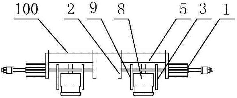
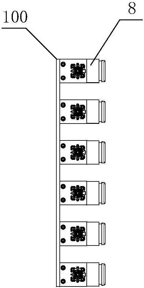
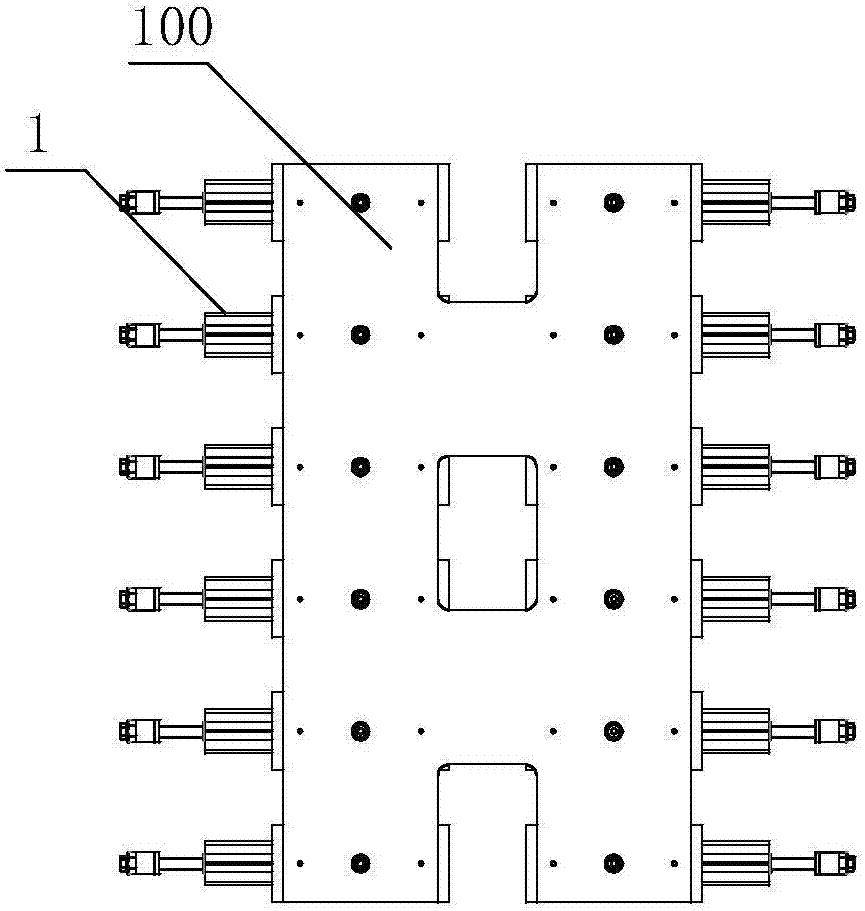
[0032] A device for reclaiming rubber parts of an injection molding machine, comprising 12 groups of grabbing units with the same structure arranged one after the other and installed on the bottom surface of the connecting plate 100. The grabbing unit includes a blow tube 8 and installed on both sides of the blow tube The main gripper 3 and the secondary gripper 9 are installed in the center of the cover plate 7 through the air inlet pipe 6 connected to the blower. The upper part of the cover plate is connected to the slide plate 5, and slide grooves 51 are provided on both sides of the slide plate to slide the main The rack 11 and the auxiliary rack 12 are provided with a circular groove in the center of the slide plate, and the gear 10 installed in the circular groove and taking the air intake pipe as the axis is respectively connected with the main rack and the auxiliary rack installed in the sliding groove The main gripper and the secondary gripper are respectively installed...


PUM


Abstract

The invention discloses a device for taking injection molding machine rubber pieces.The device comprises N sets of grabbing units which are of a same structure and are sequentially arranged front and back and installed on the bottom face of a connecting plate; each grabbing unit comprises a blowing cylinder and a main grabber and an auxiliary grabber which are installed on the two sides of the blowing cylinder, wherein the blowing cylinder is installed at the center of a cover plate through an air inlet pipe, the upper portion of the cover plate is connected with a slideway plate, the two sides of the slideway plate are provided with slide grooves which are used for installing a main rack and an auxiliary rack respectively, the center of the slideway plate is provided with a circular groove which is used for installing a gear meshed with the main rack and the auxiliary rack, the main grabber and the auxiliary grabber are installed on guide rods arranged at the bottom of the cover plate respectively, the main grabber is connected with the main rack, the auxiliary grabber is connected with the auxiliary rack, the two ends of the slideway plate are vertically connected with support plates of the guide rods, the main grabber is connected with a push rod of a sucker-rod air cylinder installed on the support plates, and the main grabber and the auxiliary grabber are driven by the push rods to achieve clamping or loosening; the grabbing units are connected with the connecting plate through the slideway plates.According to the device, the labor cost and the labor intensity are low, the working efficiency is high, the product qualification rate is high, a mold is easy to clean, and the harm of harmful gas to workers can be avoided.

Description

Technical field [0001] The invention relates to an auxiliary device of an injection molding equipment, in particular to a device for reclaiming rubber parts of an injection molding machine. Background technique [0002] In the existing production process of rubber parts, the rubber raw material is vulcanized at high temperature by the injection molding machine, and then poured into the corresponding mold cavity to form the required rubber part shape. After the rubber part is vulcanized, the rubber part is manually removed from the mold. Taking off the rubber parts has not yet formed a new type of process flow for pulling out the rubber parts. [0003] The existing problems in the manual production process are: [0004] 1. Using labor to pick up one by one, the labor cost is high, the labor intensity of the workers is high, and the production efficiency is low; [0005] 2. In the process of picking up the parts by the workers, due to the upward pulling of the rubber parts, the direc...

Claims


Application Information

Patent Timeline
Patent Type & Authority Patents(China)
IPC IPC(8): B29C45/42
CPCB29C45/4225B29C2045/4233
Inventor 李健梁鹏刘邦雄辛艳峰琚林锋贾宇坤
Owner 无锡美悦电器有限公司
Learn More