Lifting mechanism of intelligent electric clothes drying machine

A technology of intelligent electric clothes dryer and lifting mechanism, which is applied in the direction of clockwork mechanism, washing device, textile and paper making, etc. It can solve the problems of affecting the life of steel wire rope, unstable lifting and lowering of drying rod, and increased noise of motor operation, etc.

Active Publication Date: 2016-07-13
ZHEJIANG YONG HUI APPLIANCE CO LTD +1
View PDF7 Cites 9 Cited by
  • Summary
  • Abstract
  • Description
  • Claims
  • Application Information

AI Technical Summary

Problems solved by technology

In the prior art, if the steel wire rope is disorderly and irregularly wound on the reel, the steel wire rope will be subjected to irregular stress during the winding process, which will affect the life of the steel wire rope, and will also cause the motor to be overloaded, resulting in motor running noise increase; in addition, when the reel is retracting the wire rope, the position of the wire rope protruding from the two ends of the length direction of the shell is not straight, and it is easy to make the lifting of the drying rod unstable; in order to mak

Method used


Image

  • Lifting mechanism of intelligent electric clothes drying machine
  • Lifting mechanism of intelligent electric clothes drying machine
  • Lifting mechanism of intelligent electric clothes drying machine

Examples


Embodiment Construction

[0025] In order to make the object, technical solution and advantages of the present invention clearer, the present invention will be further described in detail below in conjunction with the accompanying drawings and embodiments. It should be understood that the specific embodiments described here are only used to explain the present invention, not to limit the present invention.

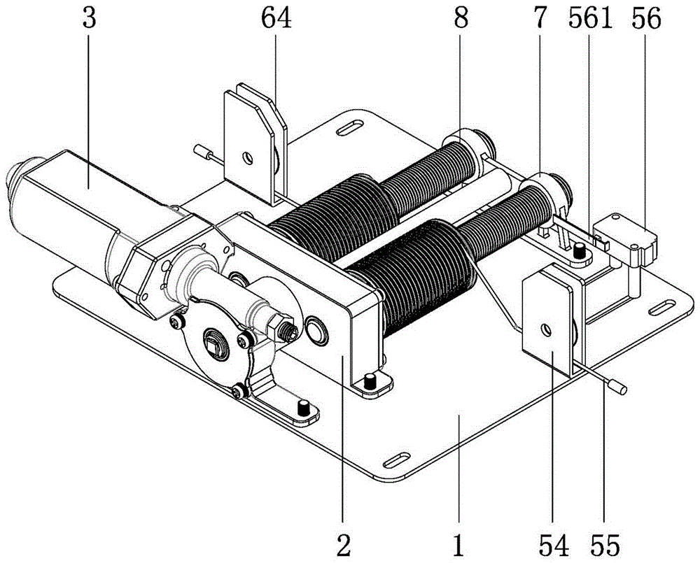
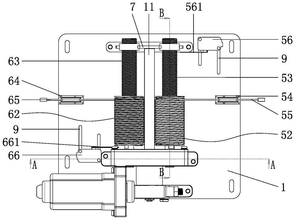
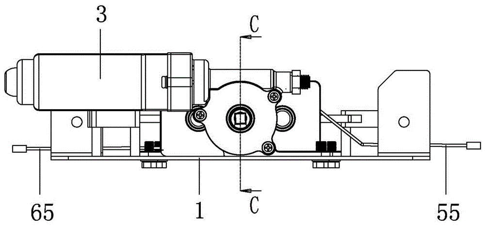
[0026] see Figure 1 to Figure 7 As shown, the embodiment of the present invention is a lifting mechanism of an intelligent electric clothes dryer, including a bottom plate 1, on which a reduction box 2 is arranged, and a reduction gear 4 driven by a motor 3 is arranged in the reduction box 2, and the reduction gear 4 is about The first reduction gear 5 and the second reduction gear 6 are meshed on both sides respectively, and the first transmission shaft 51 and the second transmission shaft 61 are fitly fitted in the center holes of the first reduction gear 5 and the second reduction gear 6 respec...


PUM


Abstract

The invention discloses a lifting mechanism of an intelligent electric clothes drying machine. The lifting mechanism comprises a bottom plate, wherein a first speed reduction gear and a second speed reduction gear are engaged on the left side and right side of a speed reduction gear positioned in a speed reduction box on the bottom plate respectively; a first transmission shaft with one end extending out of the speed reduction box and a second transmission shaft with one end extending out of the speed reduction box are mounted in the central holes of the first speed reduction gear and the second speed reduction gear in a matched and sleeved manner respectively; a first cable pulley and a first screw rod which form an integrated structure, as well as a second cable pulley and a second screw rod which form an integrated structure, are arranged on the first transmission shaft and the second transmission shaft which extend out of the speed reduction box in a sliding clearance fit manner respectively; both the tail end of the first screw rod and the tail end of the second screw rod are mounted in through holes of a supporting frame on the bottom plate in a thread-fit and sleeved manner; and a first steel wire rope and a second steel wire rope which are wound on the first cable pulley and the second cable pulley respectively extend out of the bottom plate through a first steel wire rope guide wheel and a second steel wire rope guide wheel. The lifting mechanism is compact in structure, small in noise, uniform in steel wire rope stress, stable in running, controllable in lifting stroke and good in self-locking effect.

Description

technical field [0001] The invention belongs to the technical field of intelligent electric clothes dryers, and in particular relates to a lifting mechanism of an intelligent electric clothes dryer. Background technique [0002] In the prior art, an electric clothes dryer includes a drying rod and a lifting mechanism installed in the housing of the electric clothes drying machine on the ceiling, wherein the lifting mechanism includes a driving device, a reel driven by the driving device, and a The wire rope protruding from the two ends of the body, the lower end of the wire rope is tied on the airing rod, and the other end of the wire rope is wound on the reel. Driven by the driving device, the wire rope lifts or puts down the airing rod. In the prior art, if the steel wire rope is disorderly and irregularly wound on the reel, the steel wire rope will be subjected to irregular stress during the winding process, which will affect the life of the steel wire rope, and will also...

Claims


Application Information

Patent Timeline
IPC IPC(8): D06F57/12B66D1/12B66D1/26B66D1/14B66D1/56
CPCB66D1/12B66D1/14B66D1/26B66D1/56B66D2700/0141D06F57/125
Inventor 于辉朱宏军吴和锋
Owner ZHEJIANG YONG HUI APPLIANCE CO LTD
Why Eureka
Try Eureka