Combined tent fixing peg
A fixed and combined technology, applied in tents/canopies, building types, buildings, etc., can solve the problems of inconvenient camping in the wild, easy to rotate, low tensile capacity, etc., to achieve simple structure, uniform force, The effect of strong tensile strength
- Summary
- Abstract
- Description
- Claims
- Application Information
AI Technical Summary
Problems solved by technology
Method used
Image

Examples
Embodiment Construction
[0016] The present invention will be further explained below in conjunction with the accompanying drawings and specific embodiments. It should be understood that the following specific embodiments are only used to illustrate the present invention and are not intended to limit the scope of the present invention. It should be noted that the words "front", "rear", "left", "right", "upper" and "lower" used in the following description refer to the directions in the drawings, and the words "inner" and "outer ” refer to directions towards or away from the geometric center of a particular part, respectively.
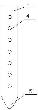
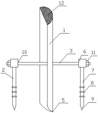
[0017] As shown in the figure, a combined tent fixing ground nail according to the present invention includes a main nail 1, an auxiliary nail 2 and a connecting bolt 3. The main nail 1 is long and the cross section of the main nail 1 is an arc 2-10 connecting holes 4 are vertically arranged on the surface of the main nail 1, and the bottom of the main nail 1 is pointed 5, and ...
PUM
 Abstract
Description
Claims
Application Information
PatSnap Eureka turns technology decisions into work you can execute. Powered by our Innovation Knowledge Graph, it runs expert workflows across engineering, life sciences, materials and intellectual property. Get your review-ready output in minutes.


