Combined piezoelectric and pressurizing electromagnetic fuel gas injection device

An injection device and combined technology, which is applied in the direction of oil supply device, charging system, combustion engine, etc., can solve the problems that affect the stability of the injection device, gas leakage, and large coverage of single-cylinder power of the engine.

Active Publication Date: 2016-07-13
HARBIN ENG UNIV
View PDF6 Cites 5 Cited by
  • Summary
  • Abstract
  • Description
  • Claims
  • Application Information

AI Technical Summary

Problems solved by technology

[0003] The current in-cylinder direct injection gas injection system mainly controls the movement of the needle valve through the internal integrated high-speed solenoid valve to realize the opening and closing of the gas injection valve, which can control the timing and amount of gas injection, and has good energy saving and emission reduction effect, but there are some problems: first, the single-cylinder power coverage of the engine is large, and only the single-nozzle jet device is used to match the limited engine power, which cannot meet the power of the engine under different working conditions and the power requirements of serialized engines; , a single high-speed solenoid valve only has two working states of on and off, and cannot complete the multi-mode control of gas injection; third, the control of the solenoid valve is affected by the hysteresis loop and the inductance of the solenoid coil, the response speed is limited, and the control accuracy of the piezoelectric control valve is limited. High, fast response; Fourth, in order to improve the degree of gas mixing, the gas injection pressure is usually increased, the existing gas injection device can not realize the adjustable injection pressure in a working cycle; Fifth, with the movement of the needle valve, the gas along the The gap between the needle valve coupling parts leaks upwards, and the leaked gas enters the control chamber, resulting in a decrease in the gas injection pressure and injection rate, which seriously affects the working stability of the gas injection device

Method used


Image

  • Combined piezoelectric and pressurizing electromagnetic fuel gas injection device
  • Combined piezoelectric and pressurizing electromagnetic fuel gas injection device
  • Combined piezoelectric and pressurizing electromagnetic fuel gas injection device

Examples


Embodiment Construction

[0028] The present invention is described in more detail below in conjunction with accompanying drawing example:

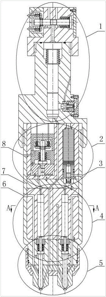
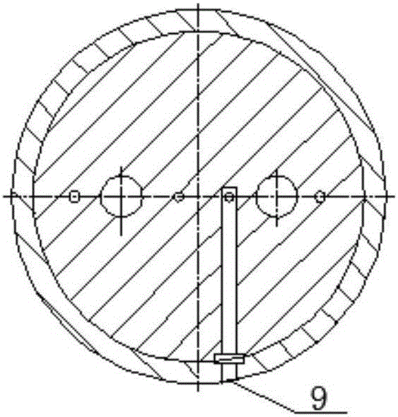
[0029] The combined piezoelectric-supercharged electromagnetic gas injection device of the present invention is mainly composed of a booster part 1, an electromagnetic-piezoelectric control part 2, a double-piston part 4, a double-needle valve nozzle part 5 and an injection device body 7. The injection device body 7 has a first low-pressure oil drain port 3, a control oil inlet 6, a second low-pressure oil drain port 8, a gas inlet 9, etc. The top view of the oil passage at the gas inlet is shown in Figure 1(b).

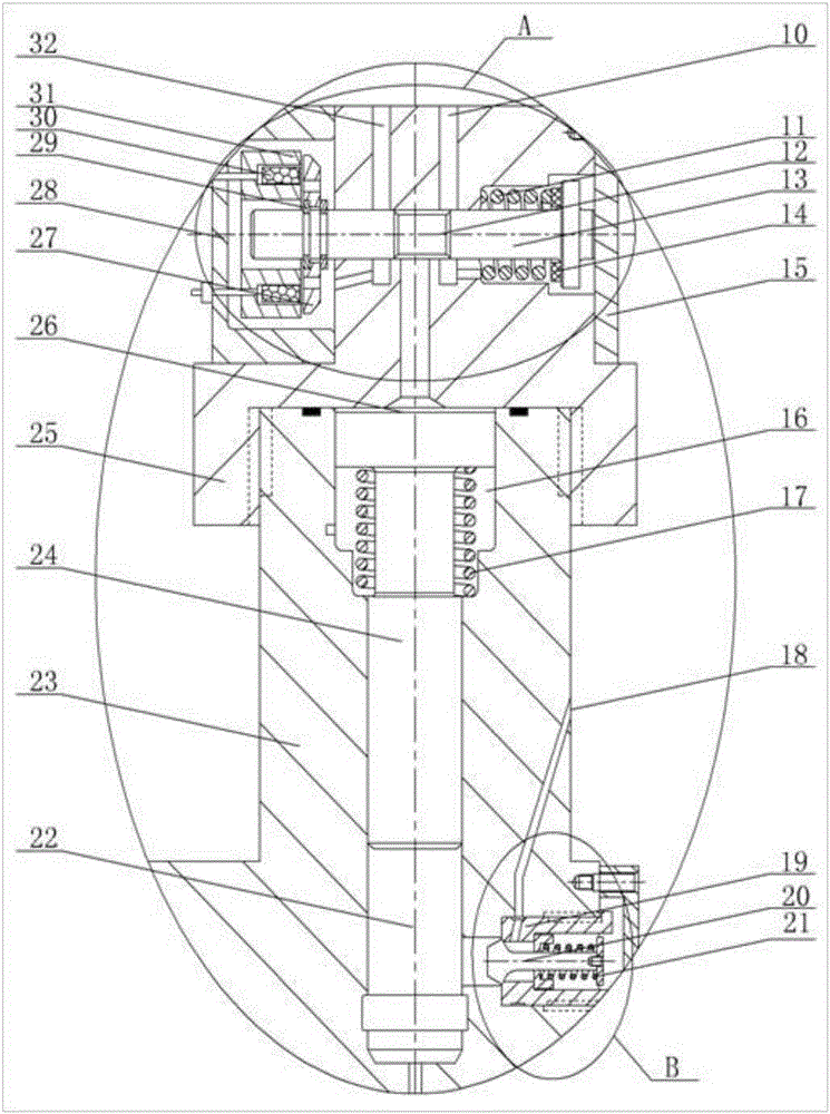
[0030] The pressurized part 1 is located above the injection device body 7, and the two are connected by threads. The booster part 1 mainly includes a solenoid valve A, an intake valve B, a booster piston spring 17, a booster piston sleeve 23, a booster piston 24, a solenoid valve seat 25, and the like. Wherein, solenoid valve A is composed of solenoid ...


PUM


Abstract

The invention provides a combined piezoelectric and pressurizing electromagnetic fuel gas injection device which comprises a pressurizing part, an electromagnetic-piezoelectric control part, a double-piston part, a double needle valve nozzle part and an injection device shell.Electromagnetic valves and a piezoelectric control valve are adopted to control the fuel gas injection process of two nozzles respectively; the nozzle controlled by the electromagnetic valves can be switched between a pressurizing mode and a non-pressurizing mode flexibly, adjustable gas injection pressure and gas injection quantity of the gas injection device can be achieved in a work cycle by adjusting the work state and work order of the pressurizing electromagnetic valve, the nozzle electromagnetic valve and the piezoelectric control valve, and the power requirements of an engine under different working conditions and series engine power requirements are met.A seal band is designed between each needle valve and a corresponding needle valve seat, part of control oil is introduced to the seal bands through an oil duct to seal fuel gas, leakage of fuel gas can be effectively prevented, meanwhile control oil in a control cavity and sealing oil at the needle valves are the same, and static leakage of the fuel oil in the control cavity and the sealing bands can be effectively prevented.

Description

technical field [0001] The invention relates to a dual-fuel engine gas injection device, in particular to a combined piezoelectric-supercharged electromagnetic gas injection device. Background technique [0002] The development of alternative fuels for engines is an effective means to solve the problems of energy shortage and environmental pollution. Natural gas and petroleum gas have become the main substitute fuels for internal combustion engines due to their abundant resources, low price, clean combustion, and high calorific value. [0003] The current in-cylinder direct injection gas injection system mainly controls the movement of the needle valve through the internal integrated high-speed solenoid valve to realize the opening and closing of the gas injection valve, which can control the timing and amount of gas injection, and has good energy saving and emission reduction effect, but there are some problems: first, the single-cylinder power coverage of the engine is la...

Claims


Application Information

Patent Timeline
Patent Type & Authority Applications(China)
IPC IPC(8): F02M21/02
CPCF02M21/0248F02M21/0254F02M21/0263Y02T10/30
Inventor 范立云彭怀利董全李文辉董晓露刘友
Owner HARBIN ENG UNIV
Why Eureka
Try Eureka