Electromagnetic and pressurization piezoelectric combined fuel gas injection device

An injection device, supercharged piezoelectric technology, applied in the direction of oil supply device, charging system, combustion engine, etc., can solve the problems of limited engine power, long transmission pipeline, large pressure fluctuation of supercharged gas, etc., to achieve simplified structure, Reduced installation space, high gas boost pressure and high gas boost efficiency

Active Publication Date: 2016-07-20
HARBIN ENG UNIV
View PDF4 Cites 0 Cited by
  • Summary
  • Abstract
  • Description
  • Claims
  • Application Information

AI Technical Summary

Problems solved by technology

[0003] The existing in-cylinder direct-injection gas injection devices mostly use high-pressure pumps to compress the gas to the specified pressure, and realize the gas injection through the solenoid valve to control the movement of the needle valve. The transmission pipeline of the device is long, and the pressure of the supercharged gas fluctuates greatly; the supercharged gas injection device can meet the requirements of high-pressure or low-pressure injection in a single cycle of gas, but it cannot meet the requirements of variability of injection pressure in a single cycle of the engine; the single-nozzle gas injection device matches the engine The power is limited, and it cannot meet the engine gas injection control requirements and the gas injection quantity requirements under different powers at the same time; although the two gas injection devices can meet the engine gas injection requirements, the size and installation position are limited by the cylinder head; the gas injection device utilizes pressure When the gas ejects from the needle valve, due to the strong compressibility of the gas, the gas injection is unstable, which is not conducive to the precise control of the movement of the needle valve; in addition, with the movement of the valve core, the gas flows through the gap between the valve core and the valve body. Leakage at the solenoid valve end increases, resulting in reduced gas injection pressure and injection rate, affecting engine power and fuel economy

Method used


Image

  • Electromagnetic and pressurization piezoelectric combined fuel gas injection device
  • Electromagnetic and pressurization piezoelectric combined fuel gas injection device
  • Electromagnetic and pressurization piezoelectric combined fuel gas injection device

Examples


Embodiment Construction

[0020] The present invention will be further described below in conjunction with accompanying drawing example:

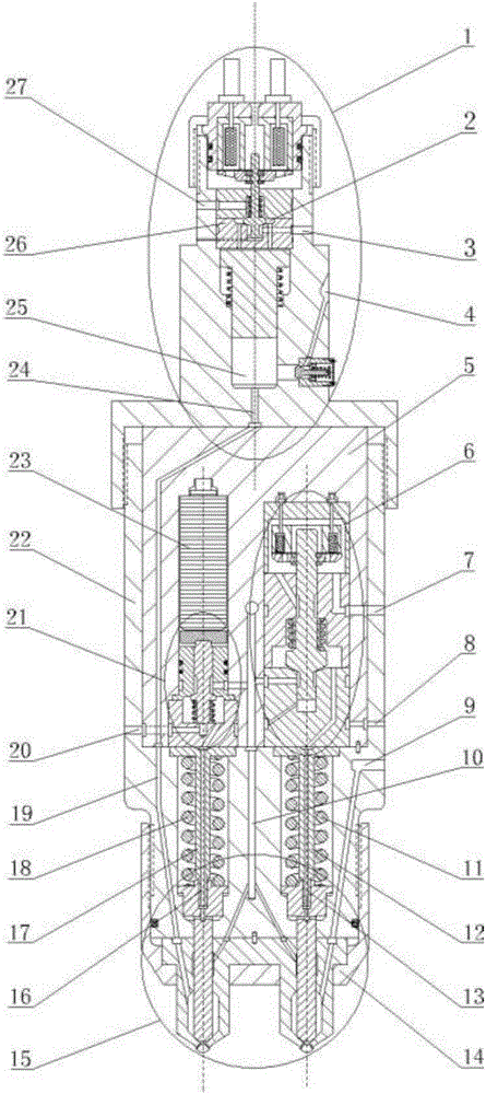
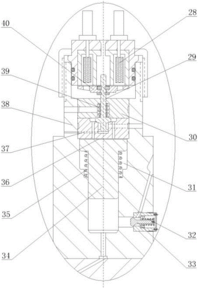
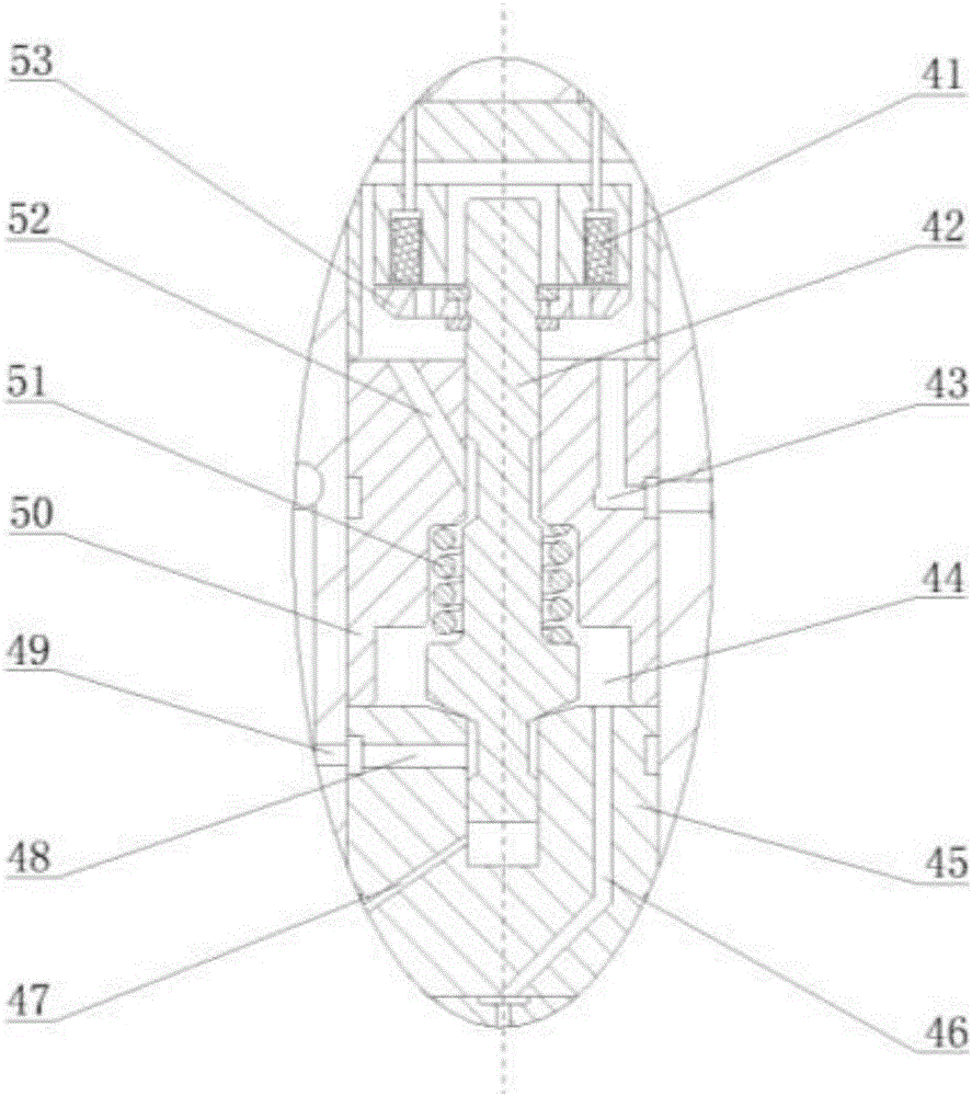
[0021] combine Figure 1-5 , The combined electromagnetic-supercharged piezoelectric gas injection device of the present invention mainly includes a gas booster part 1, an electromagnetic control part 6, a piezoelectric control part 21, a double gas nozzle part 15, a supercharging device housing 38, and a control device housing 5 , injection device housing 22, air intake passage I9, air intake passage II19, pressurized oil inlet oil passage 3, pressurized oil discharge oil passage 27, oil inlet oil passage 10.

[0022]The gas booster part 1 is composed of a booster piston 34, a booster piston upper cavity 36, a booster piston lower cavity 25, a booster piston return spring 35, a booster piston return spring chamber 31, a booster solenoid valve coil 28, and a booster piston. Armature 40, boost control valve stem 29, boost control valve return spring 39, air inlet 4,...


PUM


Abstract

The invention provides an electromagnetic and pressurization piezoelectric combined fuel gas injection device. The electromagnetic and pressurization piezoelectric combined fuel gas injection device is formed by combining a fuel gas pressurization device, an electromagnetic control device, a piezoelectric control device and two fuel gas nozzles, wherein a fuel gas pressurized by the pressurization device is charged into the fuel gas nozzle controlled by the piezoelectric control device, the unpressurized fuel gas is charged into the fuel gas nozzle controlled by the electromagnetic control device, pressure of the fuel gas injected into a combustion chamber can be changed in a single cycle of an engine, thus a mixing degree of the fuel gas and air is changed, the combustion characteristic of the fuel gas is flexible and changeable, and the changeability requirement of the injection pressure in the single cycle of the engine is met; pressurization for the fuel gas is controlled by a pressurization electromagnetic valve, and switchover between pressurized injection for the fuel gas and unpressurized injection for the fuel gas can be rapidly realized; injection for two paths of the fuel gas is controlled by the electromagnetic valve and a piezoelectric component respectively, and switchover between injection of the single fuel gas nozzle and injection of the double fuel gas nozzles can be rapidly realized; and the fuel gas is sealed by fuel oil, and avoidance for leakage of the fuel gas through a needle valve partner is facilitated, and thus the dynamic property of the engine and the economical efficiency of fuel are improved.

Description

technical field [0001] The invention relates to a dual-fuel engine gas injection device, in particular to a combined electromagnetic-supercharged piezoelectric gas injection device. Background technique [0002] The development of alternative fuels for engines is one of the very effective means to solve the problems of energy shortage and environmental pollution. Due to the advantages of abundant resources, low price and clean combustion, gaseous fuel has become an alternative fuel for engines with good development prospects. [0003] The existing in-cylinder direct-injection gas injection devices mostly use high-pressure pumps to compress the gas to the specified pressure, and realize the gas injection through the solenoid valve to control the movement of the needle valve. The transmission pipeline of the device is long, and the pressure of the supercharged gas fluctuates greatly; the supercharged gas injection device can meet the requirements of high-pressure or low-press...

Claims


Application Information

Patent Timeline
Patent Type & Authority Applications(China)
IPC IPC(8): F02M21/02
CPCF02M21/0248F02M21/0254F02M21/0263Y02T10/30
Inventor 范立云董晓露马修真扈爽彭怀利董全
Owner HARBIN ENG UNIV
Why Eureka
Try Eureka