
A hydraulic slide valve

A technology of hydraulic slide valve and valve core, applied in the field of hydraulic valve, can solve problems such as cost increase and waste of resources, and achieve the effect of saving resources and costs, ensuring matching and ensuring unity

Active Publication Date: 2017-06-06
LANZHOU UNIVERSITY OF TECHNOLOGY
View PDF6 Cites 0 Cited by
  • Summary
  • Abstract
  • Description
  • Claims
  • Application Information

AI Technical Summary

Problems solved by technology

[0004] In order to solve the problem of resource waste and cost increase caused by the overall replacement of the valve core due to the erosion and wear of the throttle groove and valve port control edge of the valve core, especially for large-sized valve cores and special valves The throttle groove of the core and the hydraulic slide valve for the control performance test of the valve port control edge, the present invention proposes a new type of hydraulic slide valve

Method used


Image

  • A hydraulic slide valve
  • A hydraulic slide valve
  • A hydraulic slide valve

Examples


Embodiment Construction

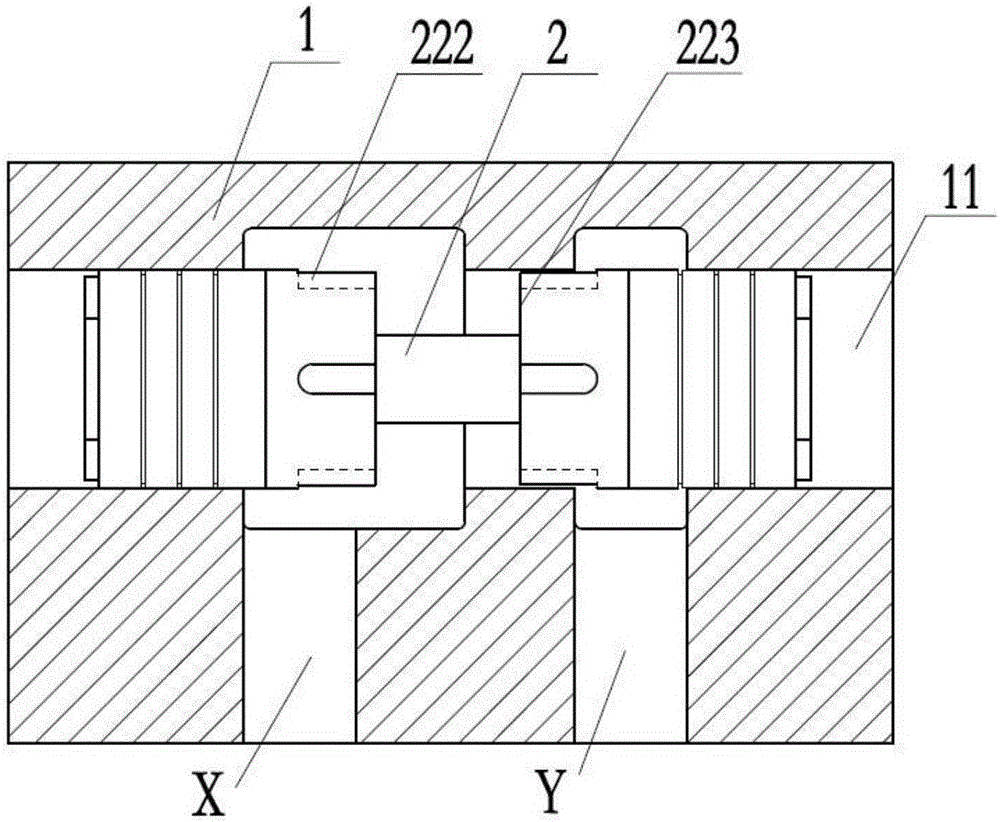
[0025] figure 1 It is a partial structural schematic diagram of the hydraulic slide valve of the present invention. The hydraulic slide valve includes a valve body 1 and a valve core 2, and the valve body 1 is provided with a valve body hole 11 and an oil passage X and an oil passage Y for oil circulation. The spool 2 is located in the valve body hole 11 and moves left and right along the axis of the valve body hole 11 to control the communication state of the oil passage X and the oil passage Y, and under the action of the throttling groove 222 and the control edge 223 of the valve port, realize Oil control. By adjusting the structural size of the throttle groove 222, the hydraulic slide valve can have different control characteristics.

[0026] During the working process of the hydraulic slide valve, when the high-pressure oil and the solid particles in the oil pass through the oil passage X and the oil passage Y, they will cause erosion and wear to the throttling groove 2...


PUM


Abstract

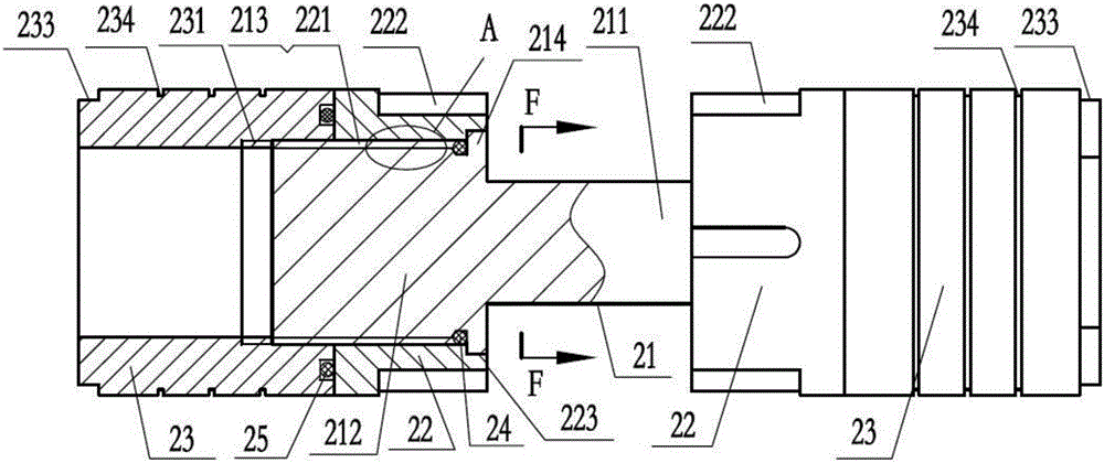
The invention belongs to the field of hydraulic valves and provides a novel hydraulic slide valve, aiming to solve the problems of resource waste and higher cost caused by overall replacement of a valve element due to the fact that a throttling groove and a valve port control edge of the valve element are subjected to erosive wear. The novel hydraulic slide valve comprises a valve body and a valve element, the valve element is provided with a throttling groove and a valve port control edge and comprises a valve element base body, a valve port body and a valve element sleeve, the valve element base body comprises a connecting rod and shoulders positioned at two ends of the connecting rod, the shoulders are detachably connected with the valve port body and the valve element sleeve, the valve port body is closer to the connecting rod, and the throttling groove and the valve port control edge are positioned on the valve port body. The novel hydraulic slide valve of a split structure is simple in structure, remarkable in erosion wear resistant effect and capable of reducing resource waste and cost.

Description

technical field [0001] The invention relates to a hydraulic valve, in particular to a hydraulic slide valve. Background technique [0002] At present, hydraulic systems are widely used in machine tool equipment, construction machinery and agricultural machinery and other fields. As one of the important components of the hydraulic system to realize the control of equipment and machinery, the hydraulic slide valve has an important impact on the hydraulic system with its control performance. [0003] The control performance of the hydraulic spool valve is affected by the size of the throttle groove and the size of the valve port. During the working process of the hydraulic slide valve, when the high-pressure oil and the solid particles in the oil flow through the valve port quickly, it will cause erosion and wear to the throttle groove of the valve core and the control edge of the valve port, causing the throttle groove Variations in size and orifice size lead to degradation ...

Claims


Application Information

Patent Timeline
Patent Type & Authority Patents(China)
IPC IPC(8): F15B13/02
CPCF15B13/02
Inventor 刘新强冀宏闵为高文科郑直贾登娉
Owner LANZHOU UNIVERSITY OF TECHNOLOGY
Learn More