Multi-way valve

A multi-way valve and valve body technology, applied in the field of multi-way valves, can solve the problems of difficult control of reaction device pressure and reaction speed, single application, high cost, etc., and achieve the effect of simple and practical structure, easy operation and reliable sealing

Active Publication Date: 2016-07-13
WUHAN HAN DE INSTR CO LTD
View PDF6 Cites 2 Cited by
  • Summary
  • Abstract
  • Description
  • Claims
  • Application Information

AI Technical Summary

Problems solved by technology

There are many kinds of valves in the existing market, but most of the existing valves have a one-valve-one-channel structure, and their application conditions are relatively single
The reaction device in the pharmaceutical manufacturing industry needs to be equipped with multiple feed pipes, and each feed pipe is equipped with a valve. The cost of multiple valves is not only high, but also the pressure and reaction speed inside the reaction device are not easy to control. One feed port, different reactants enter from the feed port, so there are problems of slow feed rate and low reaction efficiency

Method used


Image

  • Multi-way valve
  • Multi-way valve
  • Multi-way valve

Examples


Embodiment 1

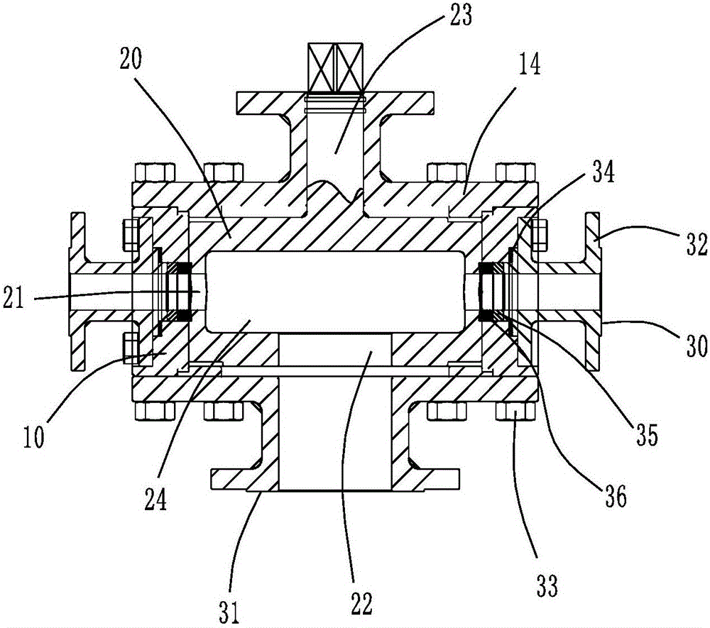
[0035] see figure 1 , figure 2 and image 3 As shown, the embodiment of the present invention provides a multi-way valve, including a valve body 10, a valve core 20, a side connecting pipe 30 and a lower connecting pipe 31,

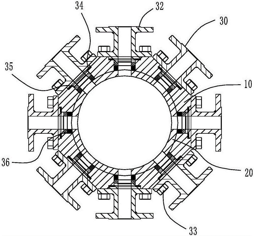
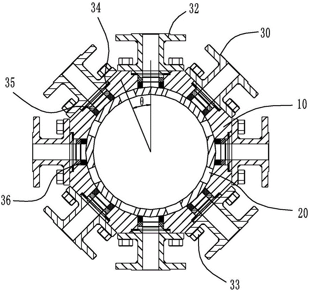
[0036] Such as Figure 4 and Figure 6 As shown, the valve body 10 is cylindrical, and the valve body 10 is provided with a cylindrical valve body cavity 11. The valve body 10 is provided with 8 valve body passages 12 at equal intervals on the same circumference, and the valve body passages 12 It communicates with the valve body cavity 11. Valve body 10 is provided with mounting hole 13, and mounting hole 13 is arranged coaxially with valve body cavity 11, and the diameter of its mounting hole 13 is larger than the diameter of spool 20, and the top of mounting hole 13 is provided with bonnet, and on bonnet 14 A through hole 15 is provided, the through hole 15, the installation hole 13 and the valve body cavity 11 are coaxially arranged, and the end ...

Embodiment 2

[0042] see Figure 9 and Figure 10 As shown, the difference between embodiment 2 and implementation 1 is:

[0043] In Embodiment 1, the valve body 10 is provided with 8 valve body passages 12 at equal intervals in the circumferential direction on the same circumference, and 8 valve core passages 21 are arranged at equal intervals in the circumferential direction of the valve core 20 on the same circumference, and the valve core passages 21 and The valve body passages 12 are connected to form 8 inlet passages.

[0044] In Embodiment 2, the valve body passages 12 of the valve body 10 are arranged on two circumferences, the two circumferences are arranged up and down, 4 valve body passages 12 are arranged at equal intervals on the upper circumference, and 4 valve passages are arranged at equal intervals on the lower circumference. body channel 12, and project the valve body channel 12 of the upper layer and the valve body channel 12 of the lower layer along the axial direction o...

Embodiment 3

[0046] The difference between embodiment 3 and embodiment 1 is:

[0047] In Embodiment 1, the valve body 10 is provided with 8 valve body passages 12 at equal intervals in the circumferential direction on the same circumference, and 8 valve core passages 21 are arranged at equal intervals in the circumferential direction of the valve core 20 on the same circumference, and the valve core passages 21 and The valve body passages 12 are connected to form 8 inlet passages.

[0048] In Embodiment 3, the valve body 10 is provided with four valve body passages 12 at intervals on the same circumference, and the distances between adjacent valve body passages 12 are not equal. A spool passage 21 is provided, and the spool passage 21 communicates with the valve body passage 12 to form 4 inlet passages. Within a certain range, the inlet passages of the valve can be opened or closed at the same time, and can also be rotated to make a certain inlet passage communicate.


PUM


Abstract

The invention discloses a multi-way valve and relates to the technical field of pipeline valves. The multi-way valve comprises a valve body and a valve core, and further comprises a valve rod, wherein a valve body cavity is formed in the valve body; a plurality of valve body channels are circumferentially formed in the valve body; the valve body channels are communicated with the valve body cavity; the valve core is mounted in the valve body cavity in a rotating manner; a plurality of valve core channels are circumferentially formed in the valve core; an outlet channel is formed in the bottom of the valve core; the valve core channels are communicated with the outlet channel; the valve core channels are communicated with the valve body channels to form a plurality of inlet channels; the inlet channels are the same in opening degree; one end of the valve rod is connected with the top end of the valve core; the other end of the valve rod is connected with a driving device; the driving device drives the valve core to rotate. The valve core channels and the valve body channels are optionally mounted in relative positions, so as to achieve that the valve core channels and the valve body channels are communicated to form the inlet channels; the multi-way valve has a plurality of inlet channels, can meet different actual demands, and is easy to operate, high in control accuracy and simple in structure.

Description

technical field [0001] The invention relates to the technical field of pipeline valves, in particular to multi-way valves. Background technique [0002] The valve is a control component in the fluid delivery system, which has functions such as cut-off, adjustment, flow diversion, reverse flow prevention, pressure stabilization, flow diversion or overflow pressure relief. There are many kinds of valves in the existing market, but most of the existing valves have a one-valve-one-channel structure, and their application conditions are relatively single. The reaction device in the pharmaceutical manufacturing industry needs to be equipped with multiple feed pipes, and each feed pipe is equipped with a valve. The cost of multiple valves is not only high, but also the pressure and reaction speed inside the reaction device are not easy to control. One feeding port, different reactants all enter from the feeding port, so there are problems of slow feeding speed and low reaction eff...

Claims


Application Information

Patent Timeline
Patent Type & Authority Applications(China)
IPC IPC(8): F16K11/085F16K27/06F16L23/024F16L23/18
CPCF16K11/085F16K27/065F16L23/024F16L23/18
Inventor 高永辉
Owner WUHAN HAN DE INSTR CO LTD
Why Eureka
Try Eureka