Three-phase three-dimensional lamination iron core of three-phase reactor

A three-dimensional laminated, three-phase reactor technology, which is applied to transformer/inductance parts, circuits, electrical components, etc., can solve the problems of unequal reactance values ​​of three-phase reactors, magnetic flux loss of three-phase reactors, and distance Incompatibility and other problems, to achieve the effect of reducing loss, reducing eddy current loss, and high utilization

Pending Publication Date: 2019-06-21
四川智翔电器有限公司
View PDF15 Cites 1 Cited by
  • Summary
  • Abstract
  • Description
  • Claims
  • Application Information

AI Technical Summary

Problems solved by technology

[0005] The purpose of the present invention is to provide a three-phase three-dimensional laminated iron core of a three-phase reactor, which solves the problem of the traditional three-phase reactor iron core, where the distance between the core columns is not equal to the three-phase reactor. The problem of unequal reactance values, and the stacking of discus in the traditional stacking method lead to the problems of magnetic flux loss and local overheating in the three-phase reactor

Method used


Image

  • Three-phase three-dimensional lamination iron core of three-phase reactor
  • Three-phase three-dimensional lamination iron core of three-phase reactor
  • Three-phase three-dimensional lamination iron core of three-phase reactor

Examples


Embodiment 1

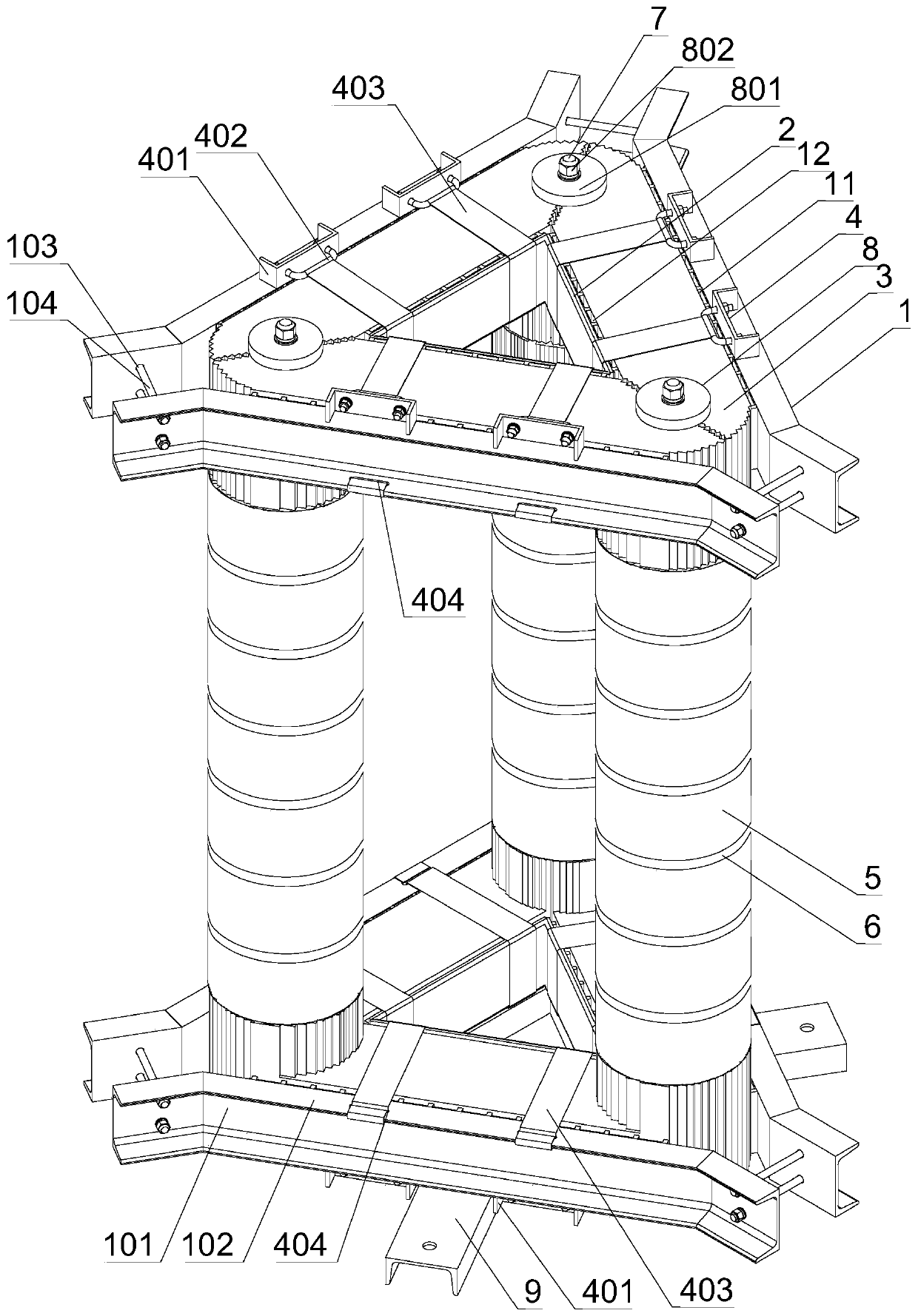
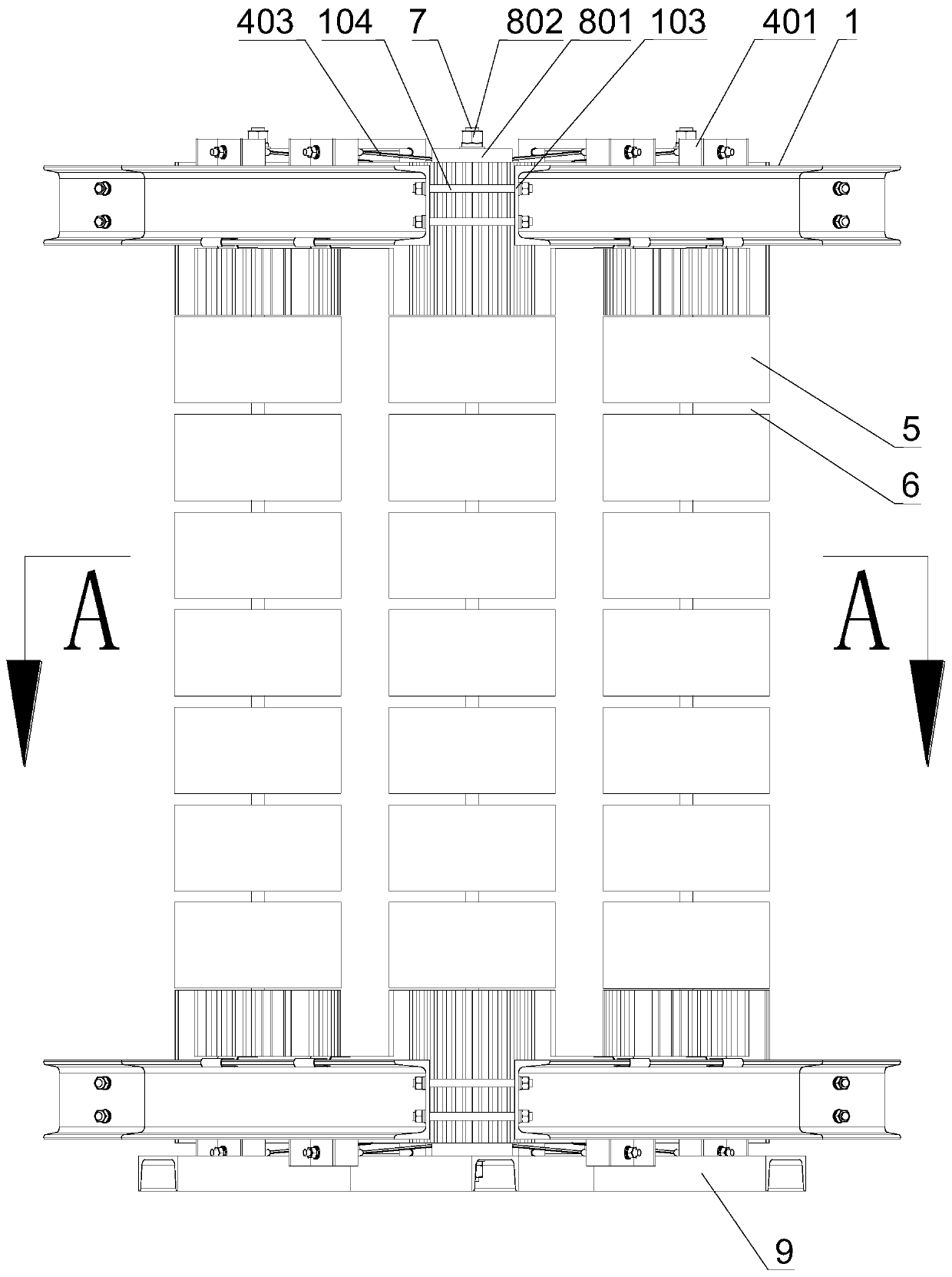
[0048] A preferred embodiment of the present invention provides a three-phase three-dimensional laminated iron core of a three-phase reactor, including an upper iron yoke, a lower iron yoke, a core column located between the upper iron yoke and the lower iron yoke, and A fixing mechanism for fixing the iron yoke and the core column, the upper iron yoke and the lower iron yoke are triangular three-phase iron yokes, and the three-phase iron yokes include three single-phase iron yokes, three single-phase iron yokes An equilateral triangle is formed by splicing two by two, and an insulating plate is arranged at the butt joint edge of the single-phase iron yoke spliced ​​in two, and the thickness of the insulating plate is 1 mm;

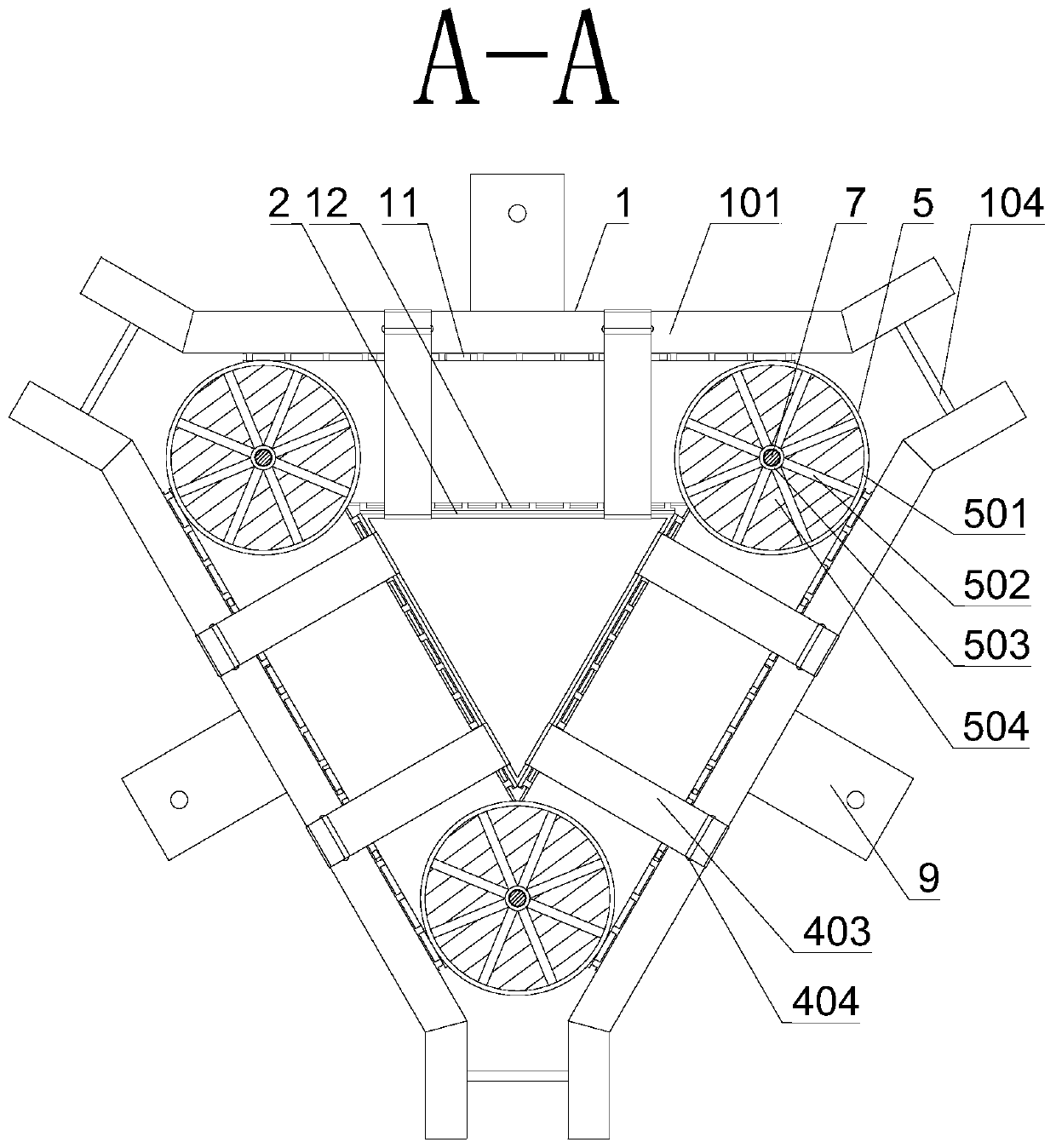
[0049] The number of the core column is three, which correspond to the three corners of the three-phase iron yoke. Gap pads 6 are alternately placed, and the through-core screw 7 is a magnetically isolated stainless steel screw, and epoxy cloth pipes are ...

Embodiment 2

[0067] This embodiment is on the basis of embodiment one, such as Figure 9 As shown, the difference is that the iron yoke laminations 3 include n rectangular laminations stacked successively from the outside to the inside, and the laminations superimposed on the i-th layer correspond to the edges of the next lamination. The angle between the connecting line and the horizontal direction is 30°, and the edge of the laminated sheets of the jth layer and the number of layers before and after it is tangent to the axial direction of the through-hole screw 7, wherein, the relationship between n and i, j is: i, j and n are all integers greater than 1, and the edge is the edge close to the adjacent single-phase iron yoke; for the laminations that do not exceed the i-th layer, they can be stacked into a cuboid, and the iron yoke of this structure When laminations 3 are superimposed, the operation is simpler.

Embodiment 3

[0069] This embodiment is on the basis of embodiment one, such as Figure 10 As shown, the difference is that the iron yoke laminations 3 include n laminations stacked one by one from the outside to the inside, and the connection between the laminations stacked on the i-th layer and the corresponding points on the edge of the next lamination The angle between the horizontal line and the horizontal direction is 30°, and the edges of the jth layer and the laminated sheets of the same number of layers before and after are tangent to the axial direction of the core screw 7, wherein the relationship between n and i, j is: i, j and n are all integers greater than 1, and the edge is the edge close to the adjacent single-phase iron yoke; for the laminations that do not exceed the i-th layer, they can also be stacked into other structures, such as inverted Isosceles ladder shape, the edges of the laminations that do not exceed the i-th layer are inscribed with a circle, and the diamet...


PUM

PropertyMeasurementUnit
thicknessaaaaaaaaaa

Abstract

The invention discloses a three-phase three-dimensional lamination iron core of a three-phase reactor, and belongs to the technical field of reactors. The three-phase three-dimensional lamination ironcore comprises an upper yoke, a lower yoke, three core posts and a fixed mechanism, wherein the core post is arranged between the upper yoke and the lower yoke, the fixed mechanism is used for fixingthe yokes and the core post, the upper yoke and the lower yoke both are triangular three-phase yokes, each three-phase yoke comprises three single-phase yokes, the three single-phase yokes are spliced and assembled to form an equilateral triangle in a paired way, the three core posts are correspondingly connected with three corners of the three-phase yoke, each core post comprises a center-penetrating screw rod, an iron cake and an air gap pad, the iron cake is arranged on the center-penetrating screw rod in a penetrating way, and the iron cakes and the air gap pads are alternatively arranged. By the three-phase three-dimensional lamination iron core, the problem that reactance values of the three-phase reactors are unequal caused by unequal distances among the core posts in the iron coreof a traditional three-phase reactor is solved, and the problems of magnetic flux loss and local overheat of the three-phase reactor caused by the iron cake laminated according to a traditional lamination mode are solved.

Description

technical field [0001] The invention belongs to the technical field of reactors, and relates to an iron core of a three-phase reactor, in particular to a three-phase three-dimensional laminated iron core of a three-phase reactor. Background technique [0002] The iron core of a traditional three-phase reactor such as Figure 5 As shown, it consists of the upper iron yoke, the core column and the lower iron yoke connected in sequence. The upper iron yoke and the lower iron yoke are both mountain-shaped iron yokes (001), which are stacked by mountain-shaped silicon steel sheets. When stacking , reserve through-hole screw holes (007) at the center and both ends; the core columns are arranged in a line in the horizontal direction, and the core columns are made of discus (005) and air gap pads (006) alternately passing through the through-hole screw , the two ends of the core column are connected with the legs of the mountain-shaped iron yoke (001). The problem with the iron cor...

Claims


Application Information

Patent Timeline
Patent Type & Authority Applications(China)
IPC IPC(8): H01F27/245
Inventor 吕迎锋刘江
Owner 四川智翔电器有限公司
Why Eureka
Try Eureka