Rapid supporting lug

A foot-supporting and fast technology, applied in the direction of supporting machines, mechanical equipment, machines/stands, etc., can solve the problems of wasteful work efficiency, reduction, and inability to achieve rapid lifting, etc. Effect

Active Publication Date: 2016-07-13
KUNSHAN BOLIAN MECHANICAL TECH CO LTD
View PDF8 Cites 2 Cited by
  • Summary
  • Abstract
  • Description
  • Claims
  • Application Information

AI Technical Summary

Problems solved by technology

[0003] However, the ordinary screw support currently used cannot be lifted and lowered quickly. Calculated with a stroke of 200mm, it often needs to rotate 20 times to reach the state of propping up and retracting, which wastes a lot of time and greatly reduces work efficiency.

Method used


Image

  • Rapid supporting lug
  • Rapid supporting lug

Examples


Embodiment Construction

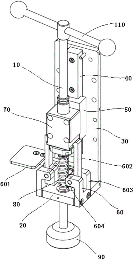
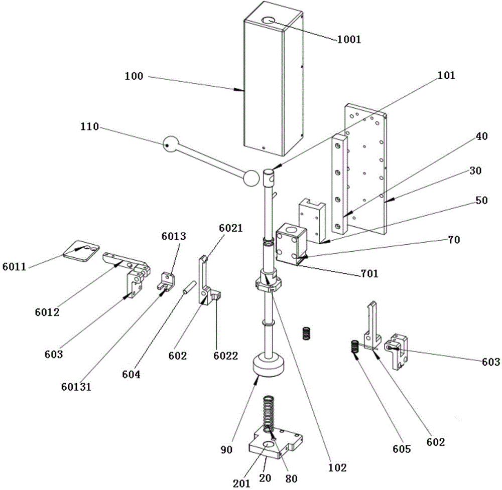
[0029] like figure 1 and figure 2 As shown, a quick support foot includes a lead screw 10, a bottom plate 20 and a side plate 30 vertically arranged on one side of the bottom plate, and the side plate is provided with a slide rail 40 and a slide rail slidably connected Slider 50; the base plate is provided with a relief opening 201, and the peripheral side of the relief opening is provided with a hook device 60; the lead screw includes a screw rod 101 and a nut 102 matched therewith, on the nut Set the inherent screw fixing block 70, the screw fixing block is fixedly connected with the slider, the screw is covered with a compression spring 80, and the screw is installed in the relief opening, so that the compression spring is positioned Between the nut and the bottom plate, a foot cup chassis 90 is provided at the lower end of the screw, and the hooking device can hook the screw fixing block and disengage from the screw fixing block. In this way, when in use, the side plate...


PUM


Abstract

The invention discloses a rapid supporting lug.The rapid supporting lug comprises a lead screw, a bottom plate and a side plate.A sliding rail and a sliding block connected with the sliding rail in a sliding mode are arranged on the side plate; a clearance opening is formed in the bottom plate, and a hook device is arranged on the periphery side of the clearance opening; the lead screw comprises a threaded rod and a nut matched with the threaded rod, the nut is fixedly sleeved with a threaded rod fixing block, the threaded rod fixing block is fixedly connected with the sliding block, the threaded rod is sleeved with a compression spring and penetrates through the clearance opening, the compression spring is located between the nut and the bottom plate, a lug cup chassis is arranged at the lower end of the threaded rod, and the hook device can be hooked on and broken away from the threaded rod fixing block.The rapid supporting lug has the function of rapid supporting and restoring, the weight pressure of a wheel when a platform works in the static state can be reduced, and supporting and restoring can be further rapidly achieved; similarly, in the 200 mm journey, supporting and restoring can be completed in the mode that the rapid supporting lug only needs to rotate by two rings, the working efficiency is improved by about ten times, and operation is quite convenient.

Description

technical field [0001] The invention relates to a support tool for temporarily propping up an object, in particular to a quick support foot with convenient operation. Background technique [0002] In daily life, there are many places that need to carry heavy objects with the help of some station equipment with wheels, such as large mobile working platforms and aerial work ladders (hereinafter referred to as platforms). When the platform reaches the destination and is used, the platform will be In a static state for a long time, in order to reduce the load pressure on the wheels when the platform is stationary for a long time, at present, ordinary screw legs are usually used to rotate until the base touches the ground to prop up the platform, so as to reduce the pressure on the wheels and use The whole platform is stable, which is convenient for the staff to walk and work on the platform. [0003] However, the common lead screw support currently used cannot be lifted and low...

Claims


Application Information

Patent Timeline
IPC IPC(8): F16M11/26
Inventor 陈鸣
Owner KUNSHAN BOLIAN MECHANICAL TECH CO LTD
Why Eureka
Try Eureka