
Heat conducting oil vapour generator

A technology of steam generator and heat transfer oil, which is applied in the steam generation method using heat carrier, etc. It can solve the problems of high water content in steam, affecting steam quality, and low heat exchange efficiency, so as to achieve high heat exchange efficiency and sufficient heat exchange Good effect, good steam quality

Inactive Publication Date: 2016-07-13
SHAOXING UNIVERSITY
View PDF0 Cites 0 Cited by
  • Summary
  • Abstract
  • Description
  • Claims
  • Application Information

AI Technical Summary

Problems solved by technology

[0002] As a new type of non-polluting energy, solar energy has broad prospects and has attracted more and more attention from governments. Solar thermal power occupies an increasingly important position in the proportion of energy due to its cleanliness and safety. Steam generators are the core of solar thermal power plants. The core component is known as the "heart". The existing steam generators all adopt the way of oil and water inlet from bottom to top, the heat exchange efficiency is not high, and the steam discharge is not smooth enough, and the water content in the steam is high, which affects the The quality of the steam is badly in need of improvement

Method used


Image

  • Heat conducting oil vapour generator
  • Heat conducting oil vapour generator

Examples


Embodiment Construction

[0011] The technical solutions of the present invention will be further specifically described below through the embodiments and in conjunction with the accompanying drawings.

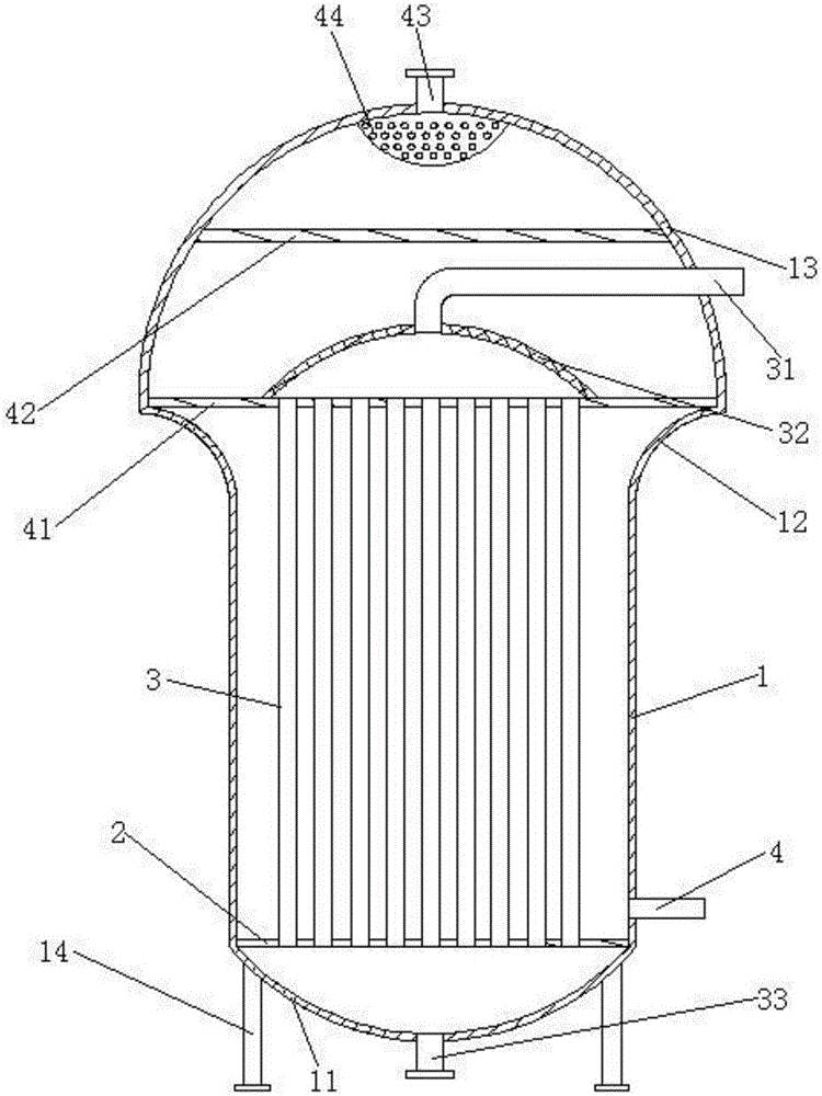
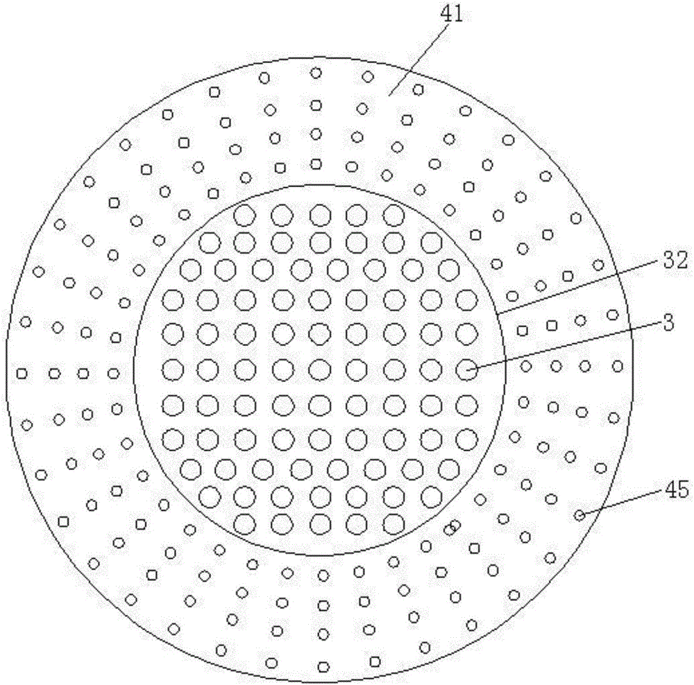
[0012] Such as figure 1 , figure 2 As shown, a heat-conducting oil steam generator includes a hollow cylindrical main cylinder 1 with openings at both ends, the upper end of the main cylinder 1 is connected with an upper cylinder 13 through a middle cylinder 12, and the lower end of the main cylinder 1 Connected with a lower cylinder 11, the middle cylinder 12 is an arc-shaped cylinder whose diameter gradually increases from bottom to top, and the arc-shaped cross-section is protruding from the side where the heat-conducting oil pipe 3 is located, and can be exchanged with the heat-conducting oil pipe 3. The motion of the heat-formed steam provides a curved route guide to speed up the steam passing through the equalizing holes 45 .

[0013] The upper cylinder 13 is a hollow hemispherical structure, ...


PUM


Abstract

The invention discloses a heat conducting oil vapour generator. The heat conducting oil vapour generator comprises a main cylinder; the upper end of the main cylinder is connected with an upper cylinder through a middle cylinder; the lower end of the main cylinder is connected with a lower cylinder; the middle cylinder is an arc-shaped cylinder of which the diameter is increased gradually from bottom to top; the upper cylinder and the lower cylinder are in hollow hemispherical structures; a lower partition plate is arranged at the junction of the lower cylinder and the main cylinder; a middle partition plate is arranged at the junction of the middle cylinder and the upper cylinder; a heat conducting oil pipe is arranged between the middle partition plate and the lower partition plate; an isolating cover which surrounds the heat conducting oil pipe is arranged in the centre of the upper surface of the middle partition plate; a plurality of layers of air uniformizing holes are formed in the periphery, positioned out of the isolating cover, of the middle partition plate; an oil inlet pipe which extends out of the side of the upper cylinder is arranged at the top end of the isolating cover; an oil outlet pipe is arranged in the centre of the bottom of the lower cylinder; a horizontal upper partition plate is arranged above the water inlet pipe in the upper cylinder; a vapour outlet pipe is arranged in the centre of the top end of the upper cylinder; a vapour-water separation cover which is opposite to the vapour outlet pipe is arranged on the inner wall of the top end of the upper cylinder. The heat conducting oil vapour generator disclosed by the invention is high in heat exchange efficiency; a vapour discharging process is smooth; the vapour quality is high.

Description

technical field [0001] The invention relates to the technical field of steam generators, in particular to a heat transfer oil steam generator. Background technique [0002] As a new type of non-polluting energy, solar energy has broad prospects and has attracted more and more attention from governments. Solar thermal power occupies an increasingly important position in the proportion of energy due to its cleanliness and safety. Steam generators are the core of solar thermal power plants. The core component is known as the "heart". The existing steam generators all adopt the way of oil and water inlet from bottom to top, the heat exchange efficiency is not high, and the steam discharge is not smooth enough, and the water content in the steam is high, which affects the The quality of the steam is in dire need of improvement. Contents of the invention [0003] The object of the present invention is to overcome the shortcomings of the above-mentioned prior art, and provide a ...

Claims


Application Information

Patent Timeline
Patent Type & Authority Applications(China)
IPC IPC(8): F22B1/16
CPCF22B1/16
Inventor 何绍木张新华
Owner SHAOXING UNIVERSITY
Learn More