A retroreflective mark measuring instrument
A measuring instrument and retro-reflection technology, applied in the field of retro-reflection sign measuring instruments, can solve the problems of limited moving space, large size of the light detector, and great influence of the detector, and achieve the effects of stable position, convenient and simple operation, and accurate measurement.
- Summary
- Abstract
- Description
- Claims
- Application Information
AI Technical Summary
Problems solved by technology
Method used
Image

Examples
Embodiment 1
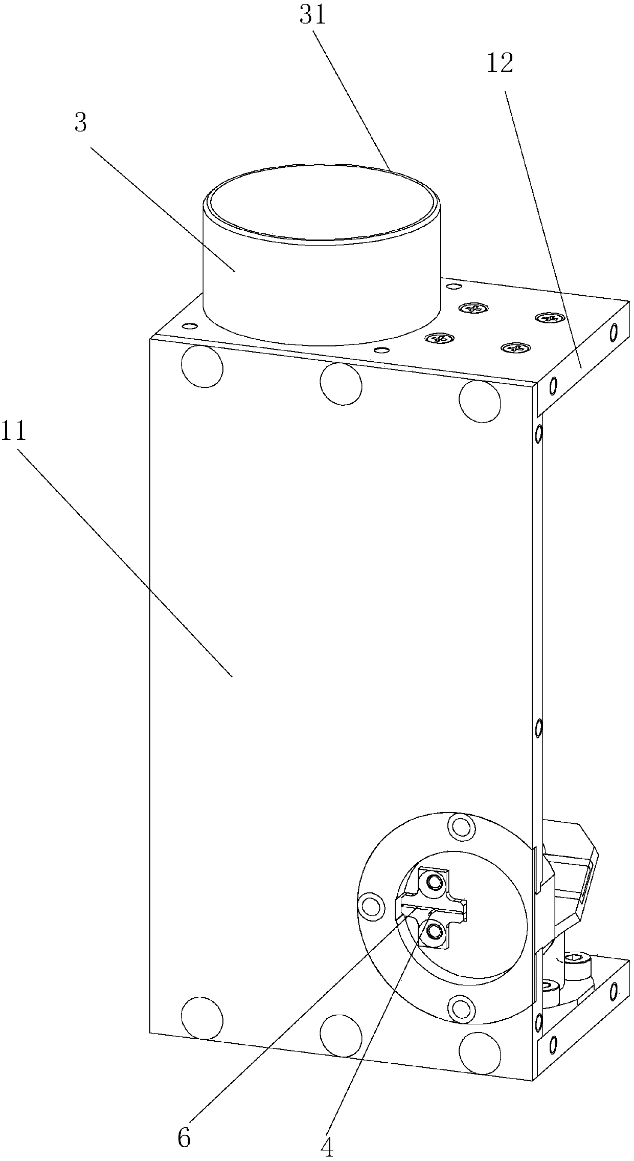
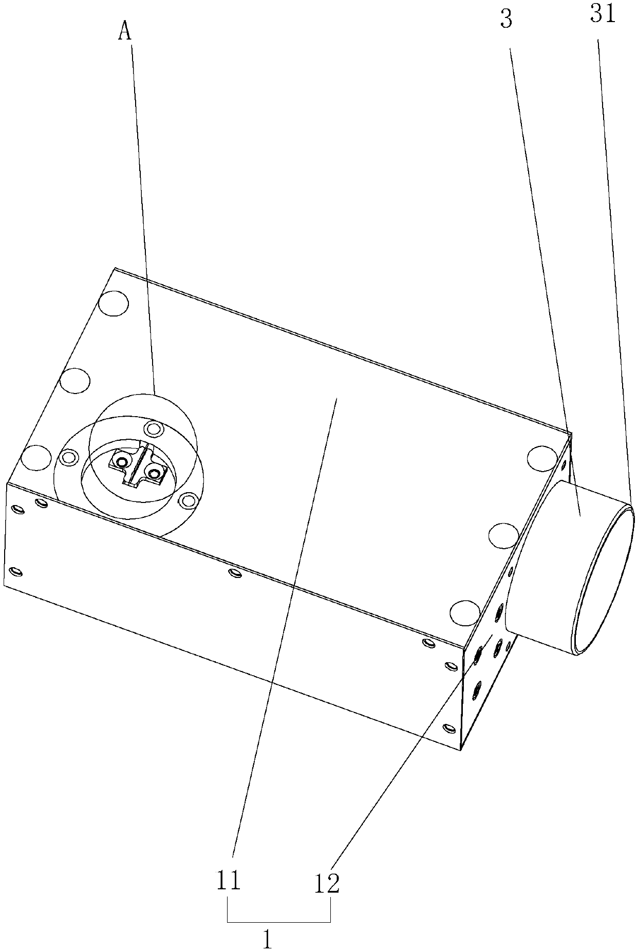
[0035] Embodiment 1: a kind of retroreflection mark measuring instrument, such as figure 2 and image 3 As shown, it includes an optical dark box 1 and a light source, and the light source is arranged in the optical dark box 1 .
[0036] The surface of the optical dark box 1 is provided with an opening, and a sample made of a retroreflective material is placed in the opening, and the opening is blocked by the sample. The optical dark box 1 is fixedly connected with a plurality of optical fibers 4 for extracting the light reflected by the sample, each optical fiber 4 corresponds to an observation angle and each optical fiber 4 is connected with a photodetector for detecting the light extracted by the optical fiber 4 .
[0037] When testing the sample, the sample reflects the light emitted by the light source to the optical fiber 4 in the adjustment groove 9, and the optical fiber 4 draws the reflected light out, projects it to the corresponding detector, and detects it throug...
Embodiment 2
[0039] Embodiment 2: as figure 1 As shown, when there is only one optical fiber 4, the fixing assembly 5 can be opened, the optical fiber 4 in the adjustment groove 9 can be fine-tuned, adjusted to the required observation angle, and then the optical fiber 4 can be fixed by the fixing assembly 5, so that different observation The angle eliminates the need to adjust the position of the photodetector. The optical fiber 4 is relatively thin, and the required adjustment space is small, and the range of each adjustment of the placement angle of the sample is small, and the reflected light is relatively close. Using the optical fiber 4 to lead out can make the emitted light projected onto the photodetector more accurately , to ensure more accurate measurement.
Embodiment 3
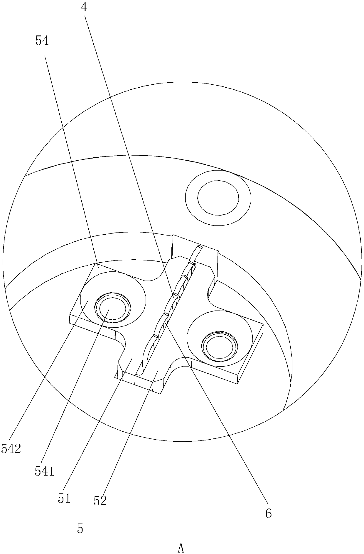
[0040] Embodiment 3: a kind of clamp assembly 5, such as image 3 As shown, a left clamping plate 51 and a right clamping plate 52 are included, and a strip-shaped clamping groove 6 is formed between the left clamping plate 51 and the right clamping plate 52 .
[0041] A side of the left clamping plate 51 away from the clamping groove 6 and a side of the right clamping plate 52 away from the clamping groove 6 both extend outward to form a fixing plate 54 with a fixing hole 541 . The width of left clamping plate 51 and right clamping plate 52 itself is not wide, and fixing hole 541 is inconveniently arranged, and fixing plate 54 is positioned at the middle part of left clamping plate 51 and right clamping plate 52 respectively, and the length of fixing plate 54 Smaller than the width of the left clamping plate 51 and the right clamping plate 52 , the overall orthographic projection is roughly T-shaped, and the diameter of the fixing hole 541 is basically the same as the length ...
PUM
 Abstract
Description
Claims
Application Information
 - R&D
- Intellectual Property
- Life Sciences
- Materials
- Tech Scout
- Unparalleled Data Quality
- Higher Quality Content
- 60% Fewer Hallucinations
Browse by: Latest US Patents, China's latest patents, Technical Efficacy Thesaurus, Application Domain, Technology Topic, Popular Technical Reports.
© 2025 PatSnap. All rights reserved.Legal|Privacy policy|Modern Slavery Act Transparency Statement|Sitemap|About US| Contact US: help@patsnap.com