Optical suspension-type microballoon rising and supporting method and device

A technology of optical levitation and microspheres, which is applied in the direction of acceleration measurement using inertial force, can solve the problem of time-consuming, and achieve the effect of improving the success rate, saving costs, and being highly repeatable.

Active Publication Date: 2016-07-13
ZHEJIANG UNIV
View PDF5 Cites 19 Cited by
  • Summary
  • Abstract
  • Description
  • Claims
  • Application Information

AI Technical Summary

Problems solved by technology

The suspension process takes a long time, and it needs to be observed by an imaging system such as a microscope to determine whether the suspension of the microspheres is successful

Method used


Image

  • Optical suspension-type microballoon rising and supporting method and device
  • Optical suspension-type microballoon rising and supporting method and device
  • Optical suspension-type microballoon rising and supporting method and device

Examples


Embodiment Construction

[0034] Further illustrate the present invention below in conjunction with accompanying drawing.

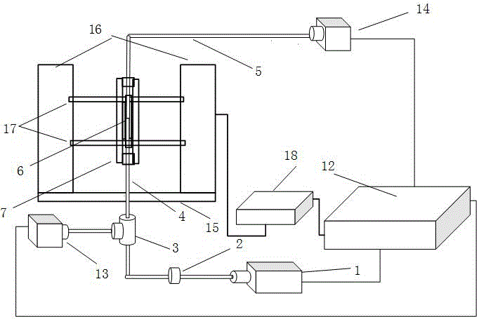
[0035] A starting device for optically suspended microspheres, including an optical trap module, an electromagnetic collision module, and a controller module; the electromagnetic collision module is used to separate the microspheres from the substrate surface, the optical trap module is used to capture the microspheres, and the controller On the one hand, the module drives the electromagnetic collision module and the optical trap module; on the other hand, it monitors the optical power of the optical trap module in real time, and controls the working state of the electromagnet in the electromagnetic collision module.

[0036] Such as figure 1 As shown, the optical trap module includes a laser 1, an optical isolator 2, a 1:99 beam splitter 3, an incident optical fiber 4, a docking optical fiber 5, an optical trap sensing substrate 6, and an optical trap sensing substrate clamp 7; ...


PUM


Abstract

The invention discloses an optical suspension-type microballoon rising and supporting method and device, and the method and device can be used for the quick rising and supporting of a light-trap accelerator microballoon. The device can easily obtain a big acceleration, needed when the microballoon needs to leave from the surface of the microballoon, through employing an electromagnetic collision method. The repeatability of collision is higher, so the device can achieve the quick separation and suspension of the microballoon. The device employs the change amount of the coupling optical power of a single-beam light trap and an abut joint optical fiber as the effective criteria for judging whether the microballoon is suspended successfully or not. The device is advantageous in that the device employs a single electromagnetic apparatus to quickly and repeatedly achieving the optical suspension of the microballoon, does not need a conventional microscope imaging structure and an expensive piezoelectric vibration device, and is high in controllability and repeatability of the microballoon.

Description

technical field [0001] The invention relates to a device based on an electromagnetic collision method to realize rapid launching of light-suspended microspheres, and belongs to the fields of inertial measurement technology, optical engineering and microparticle suspension. Background technique [0002] The optical trap accelerometer uses a focused laser beam to capture the microsphere, and obtains the acceleration information of the inertial component by measuring the position of the microsphere or the force of the optical trap. According to the environment of the microsphere, the optical trap accelerometer can be divided into the optical trap liquid floating accelerometer and the optical trap suspension accelerometer, and the environment of the microsphere is liquid, gas or vacuum respectively. Compared with the optical trap liquid floating accelerometer, the optical trap floating accelerometer overcomes the Brownian motion of the particles in the liquid and the molecular v...

Claims


Application Information

Patent Timeline
Patent Type & Authority Applications(China)
IPC IPC(8): G01P15/03
CPCG01P15/03
Inventor 胡慧珠傅振海葛晓佳舒晓武刘承
Owner ZHEJIANG UNIV
Why Eureka
Try Eureka