Refraction and reflection type large aperture and large field of view imaging system

An imaging system and large-aperture technology, applied in optical components, optics, instruments, etc., can solve the problems of small field of view, long length of optical system, etc., to achieve the effect of ensuring image quality, shortening optical length, and facilitating high-speed tracking control

Inactive Publication Date: 2016-07-13
NANJING INST OF ASTRONOMICAL OPTICS & TECH NAT ASTRONOMICAL OBSE
View PDF5 Cites 20 Cited by
  • Summary
  • Abstract
  • Description
  • Claims
  • Application Information

AI Technical Summary

Problems solved by technology

Aiming at the problems of small field of view and long length of optical system in the current catadioptric optical imaging system, the present invention designs a catadioptric optical imaging system with large diameter, large field of view and short lens barrel

Method used


Image

  • Refraction and reflection type large aperture and large field of view imaging system
  • Refraction and reflection type large aperture and large field of view imaging system
  • Refraction and reflection type large aperture and large field of view imaging system

Examples


Embodiment 1

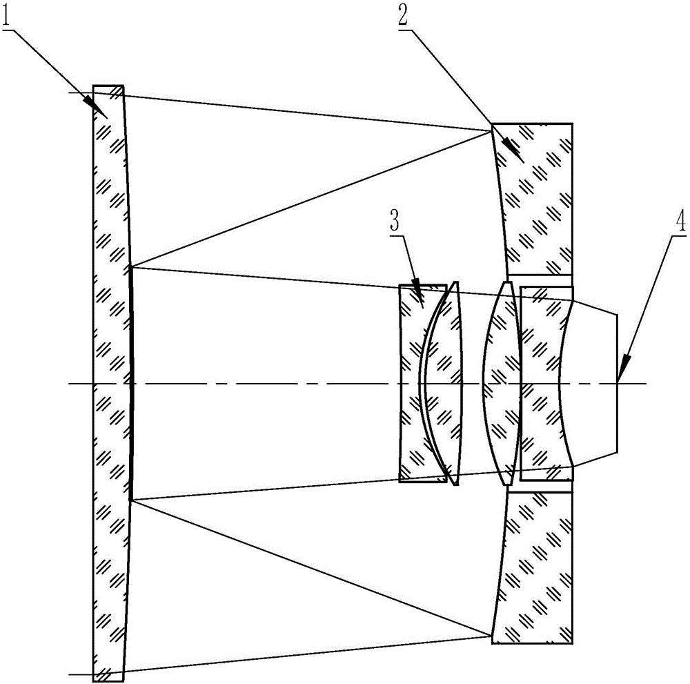
[0027] Embodiment 1, catadioptric large-aperture large-field imaging system, such as figure 1 As shown, an optical system diagram of a catadioptric large-aperture large-field imaging system of the present invention is given, which includes a refractive correction plate 1, a reflective primary mirror 2, and a refractive correction plate arranged sequentially from the object side to the image side. Type correction lens group 3, focal plane 4. The refraction correction plate 1 is located on the left side of the reflective main mirror 2 , and the refraction correction mirror group 3 is located in the through hole at the center of the reflective main mirror 2 . The refraction correction plate 1, the reflective main mirror 2 and the refraction correction mirror group 3 are coaxially arranged. The incident light irradiates the reflective primary mirror 2 through the refractive correction plate 1, and the reflective primary mirror 2 reflects the light to the reflective secondary mirr...


PUM


Abstract

The invention relates to a refraction and reflection type large aperture and large field of view imaging system. The refraction and reflection type large aperture and large field of view imaging system is characterized in that a refraction type correction plate, a reflection type primary mirror and a refraction type correction mirror group are successively arranged along an optical axis from the outside to the inside; the central area of the second surface of the correction plate is plated with a reflective coating layer, and becomes a reflection type secondary mirror; an incident light beam irradiates to the reflection type primary mirror through the refraction type correction plate; the reflection type primary mirror reflects the incident light beam to the reflection type secondary mirror; and the reflection type secondary mirror reflects the light beam to the refraction type correction mirror group, and then the light beam passing through the refraction type correction mirror group is converged on a focal plane of an optical system. The refraction and reflection type large aperture and large field of view imaging system sets the refraction type correction plate within the focus of a reflection type spherical main mirror and takes the central area of the second surface of the correction plate as the reflection type secondary mirror and the diaphragm, thus having the advantages of ultra-short lens barrel and large field of view, and being able to be widely applied to the astronomy, aviation, security and protection, and other photoelectric imaging fields. The refraction and reflection type large aperture and large field of view imaging system can realize aberration reducing design for a 11DEG-15DEG field of view. However, the field of view for a traditional refraction and reflection type imaging system is only 3DEG-4DEG.

Description

technical field [0001] The invention relates to a catadioptric large-diameter and large-field imaging system, which belongs to the technical field of photoelectric imaging. This invention is funded by the National Natural Science Foundation of China (11273040). Background technique [0002] Optical imaging systems can be divided into three types: refractive, reflective and catadioptric, each with its own characteristics: [0003] Refractive optical imaging system is composed of transmissive optical elements, and the aberration is corrected through the curvature, refractive index and dispersion coefficient of the optical elements. The advantage is that there is no central occlusion, and there are many optimization parameters available to achieve a larger field of view. The disadvantage is that it is limited by material uniformity, stress, processing, gluing and other processes, and the caliber is relatively small. [0004] The reflective optical imaging system uses the surf...

Claims


Application Information

Patent Timeline
Patent Type & Authority Applications(China)
IPC IPC(8): G02B17/08
CPCG02B17/0808G02B17/0856
Inventor 寇松峰杜锬淼王国民姜翔
Owner NANJING INST OF ASTRONOMICAL OPTICS & TECH NAT ASTRONOMICAL OBSE
Why Eureka
Try Eureka