Projector with bulb detached laterally
A technology of projectors and light bulbs, applied in optics, instruments, projection devices, etc., can solve the problems of falling into eyes or other parts of the body, harming the safety of operators, etc., and achieve the effect of avoiding falling or losing and facilitating maintenance
- Summary
- Abstract
- Description
- Claims
- Application Information
AI Technical Summary
Problems solved by technology
Method used
Image

Examples
Embodiment 1
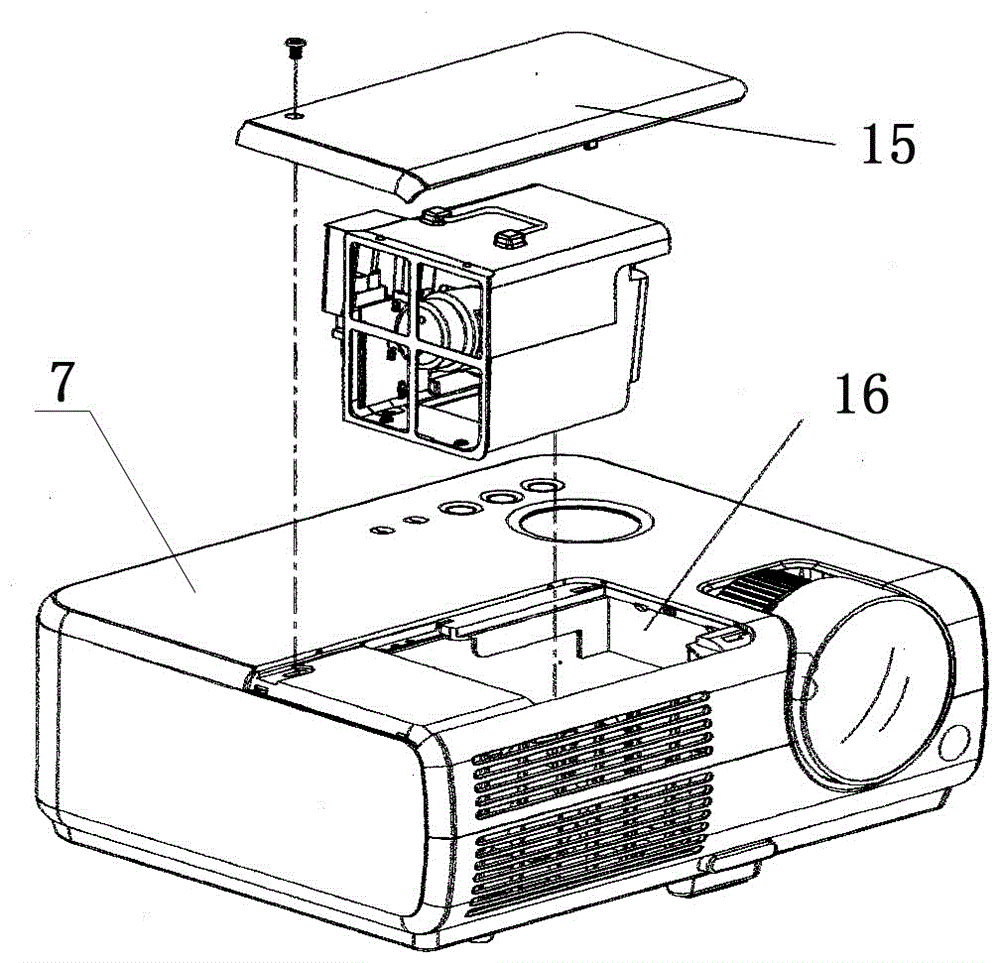
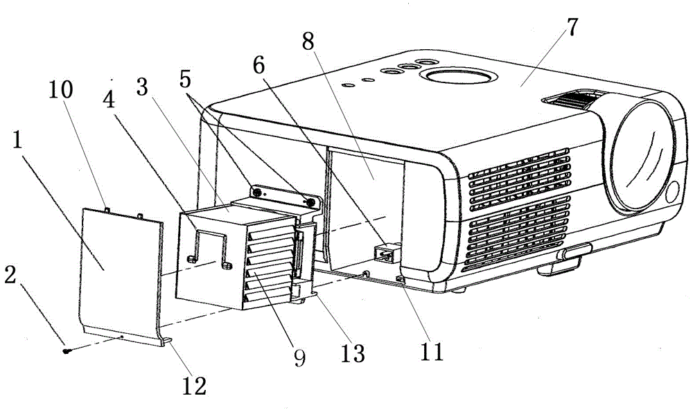
[0017] The present invention is a projector with a side-mounted bulb, comprising a bulb cover 1, a cover screw 2, a bulb assembly 3, a handle 4, an assembly fixing screw 5, a bulb power socket 6, and a projector 7. On the side of the projector 7, there is The side opening 8 is provided with a light bulb power socket 6; the side has a side opening 8 in which the light bulb assembly 3 can be inserted or pulled out; the light bulb assembly 3 is connected to the projector 7 with assembly fixing screws 5, and the light bulb assembly There are cooling holes 9, positioning posts 13, power plugs and handles 4 on 3; there is a light bulb in the light bulb assembly 3, after the light bulb assembly 3 is inserted into the side opening 8, the power plug is inserted into the light bulb power socket 6 at the same time; there is a light bulb on the side opening 8 The cover plate 1 has buckles 10 on the bulb cover plate 1, and the buckle 10 clamps the bulb cover plate 1 on the projector and fix...
Embodiment 2
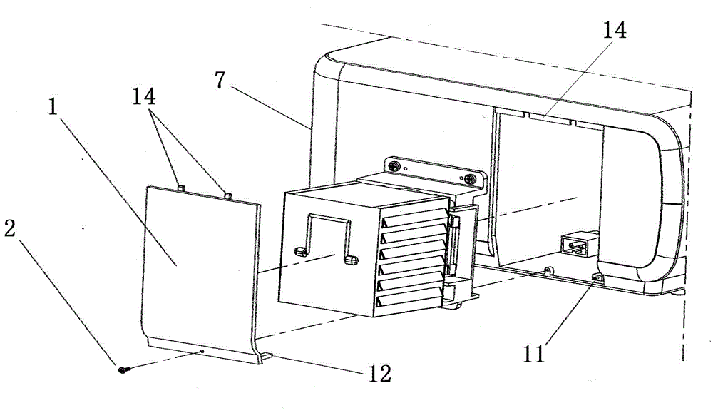
[0019] According to a kind of side-removable bulb projector described in Embodiment 1, a safety switch 11 is provided on the projector 7, and a safety switch ejector rod 12 is provided on the bulb cover 1. When the bulb assembly 3 is inserted, the switch is turned on, and the projection The projector can work normally, and the switch is disconnected when the bulb assembly 3 is pulled out, and all power is cut off in the projector to prevent electric shock accidents.
Embodiment 3
[0021] attached image 3 It is a schematic diagram of the structure of Embodiment 3 of the present invention. According to the side-mounted bulb projector described above, the projector 7 and the bulb cover 1 are connected by a hinge 14; question.
[0022] To sum up, the opening of the bulb in the present invention is placed on the side of the projector, and the maintenance personnel can stand on the side to disassemble and assemble, so that the maintenance of the bulb assembly and the replacement of the bulb can be easily realized, and the hazards of bulb debris and foreign objects can be avoided. Maintenance personnel.
PUM
 Abstract
Description
Claims
Application Information