
Front maintenance LED display module

A display module and front-maintenance technology, applied in the direction of instruments, identification devices, etc., can solve problems such as damage, mechanical stress deformation of modules, hidden dangers of product reliability, etc.

Active Publication Date: 2016-07-13
SHENZHEN EASTAR ELECTRONICS
View PDF9 Cites 7 Cited by
  • Summary
  • Abstract
  • Description
  • Claims
  • Application Information

AI Technical Summary

Problems solved by technology

Since the magnetic-absorbing structure fixes the module through the suction force between the magnets, in order to ensure a better installation flatness of the module, the distribution of the magnets must be uniform, and a large suction force must be ensured. In order to achieve removal, the removal tool must be The suction of the module should be greater. Not only must heavy metals be installed inside the module to ensure the suction, but also the suction generated at both ends will cause the module to be deformed or even damaged due to the large mechanical stress; especially for products used outdoors, in order to To achieve the performance of outdoor protection, its magnetic attraction is stronger, which not only increases the cost, but also poses a great hidden danger to product reliability

Method used


Image

  • Front maintenance LED display module
  • Front maintenance LED display module

Examples


Embodiment Construction

[0021] In order to facilitate the understanding of the present invention, the present invention will be described more fully below with reference to the associated drawings. Preferred embodiments of the invention are shown in the accompanying drawings. However, the present invention can be embodied in many different forms and is not limited to the embodiments described herein. On the contrary, the purpose of providing these embodiments is to make the disclosure of the present invention more thorough and comprehensive.

[0022] It should be noted that when an element is referred to as being “fixed” to another element, it can be directly on the other element or there can also be an intervening element. When an element is referred to as being "connected to" another element, it can be directly connected to the other element or intervening elements may also be present. The terms "vertical," "horizontal," "left," "right," and similar expressions are used herein for purposes of ill...


PUM


Abstract

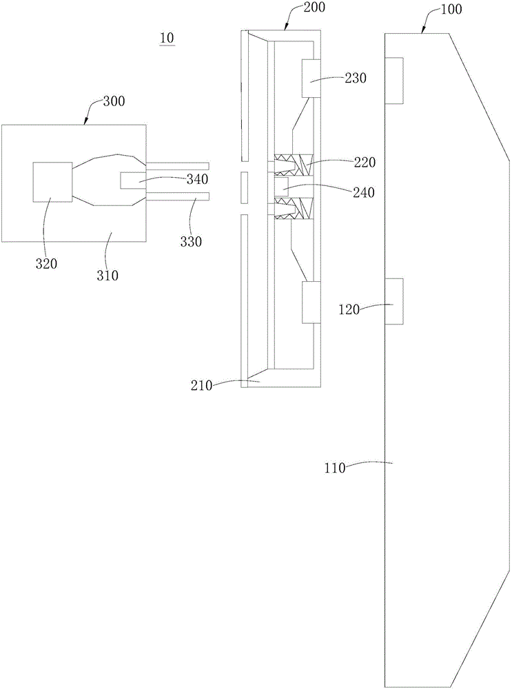
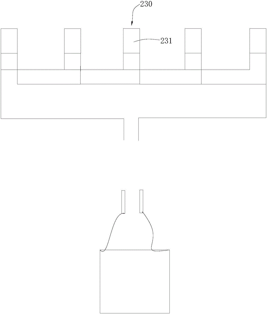
The invention discloses a front maintenance LED display module. The front maintenance LED display module comprises an LED box body, a module assembly and a dismounting assembly, wherein the LED box body comprises a box body and a permanent magnet; the permanent magnet is arranged at the box body; the module assembly comprises a bottom shell, a plug connector, an electromagnet and a first magnetic part; the bottom shell covers the box body; the electromagnet is fixed on the bottom shell and magnetically connected with the permanent magnet; the plug connector is arranged at the bottom shell and electrically connected with the electromagnet; the first magnetic part is arranged at the bottom shell; the dismounting assembly comprises a shell, a power source, an contact pin and a second magnetic part; the power source is arranged at the shell; the contact pin is arranged at the shell and electrically connected with the power source; the contact pin is used for conducting and demagnetizing the electromagnet when the contact pin is in plug-in connection with the plug connector and the electricity is conducted; and the second magnetic part is arranged at the shell and used for magnetically connecting with the first magnetic part. The front maintenance LED display module disclosed by the invention has the advantages that dismounting and mounting can be simply, conveniently and rapidly realized; and in addition, the mechanical strength of the integral structure is high.

Description

technical field [0001] The invention relates to the technical field of display modules, in particular to a front maintenance LED display module. Background technique [0002] At present, there are two main methods for the front maintenance of LED display modules at this stage: the first one is a lock-type structure, that is, a tool is used to insert the module from the front of the module, the module opens a hole, and the tool is inserted through the tool. Turn the lock structure installed at the bottom of the module to disassemble the module from the front. However, because of the lock structure, the disassembly tool of the lock structure needs to have strong structural strength, so it cannot be used for smaller The spacing, usually below 6mm, cannot be used, and the installation contact points are less, and the flatness of the module is poor. [0003] The second is the magnetic-absorbing structure. By installing several permanent magnets on the bottom of the module and th...

Claims


Application Information

Patent Timeline
IPC IPC(8): G09F9/33
CPCG09F9/33
Inventor 陈麟龙宗伟
Owner SHENZHEN EASTAR ELECTRONICS
Learn More