
Press key structure

A key and keycap technology, applied in the field of key structure, can solve the problems of poor hand feel, difficult assembly, lack of feedback of step difference, etc., to achieve the effect of improving feasibility and convenience, and improving the feeling of pressing

Inactive Publication Date: 2016-07-13
DARFON ELECTRONICS (SUZHOU) CO LTD +1
View PDF4 Cites 3 Cited by
  • Summary
  • Abstract
  • Description
  • Claims
  • Application Information

AI Technical Summary

Problems solved by technology

However, the thin film circuit layer is easily damaged by frequent use or improper application of force, and is difficult to repair
When the trigger circuit corresponding to a key in the thin film circuit layer is damaged, the corresponding trigger circuit cannot be repaired for an individual key, but the thin film circuit layer of the entire keyboard must be replaced, which makes the maintenance cost relatively high
Furthermore, when the user presses the keycap to trigger the thin film circuit layer, there is a lack of distinct level difference feedback, resulting in a poor pressing feel, which cannot satisfy the user's sense of control during the game operation.
[0003] In addition, the thin film circuit layer is made of soft material, which cannot be used as a structural support and mechanical coupling element. Therefore, the conventional keyboard structure usually needs to add a hard bottom plate, which makes the overall structure more complicated and relatively difficult to assemble.

Method used


Image

  • Press key structure
  • Press key structure
  • Press key structure

Examples


Embodiment Construction

[0024] The following descriptions of the various embodiments refer to the accompanying drawings to illustrate specific embodiments in which the present invention can be practiced. The directional terms mentioned in the present invention, such as "upper", "lower", "front", "rear", "left", "right", "side", etc., are only referring to the directions of the attached drawings. Therefore, the directional terms used are used to illustrate and understand the present invention, but not to limit the present invention.

[0025] In the following embodiments, the same parts are denoted by the same symbols in different drawings.

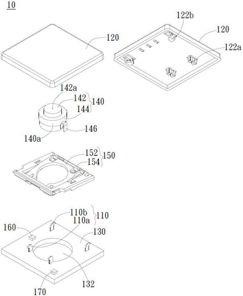
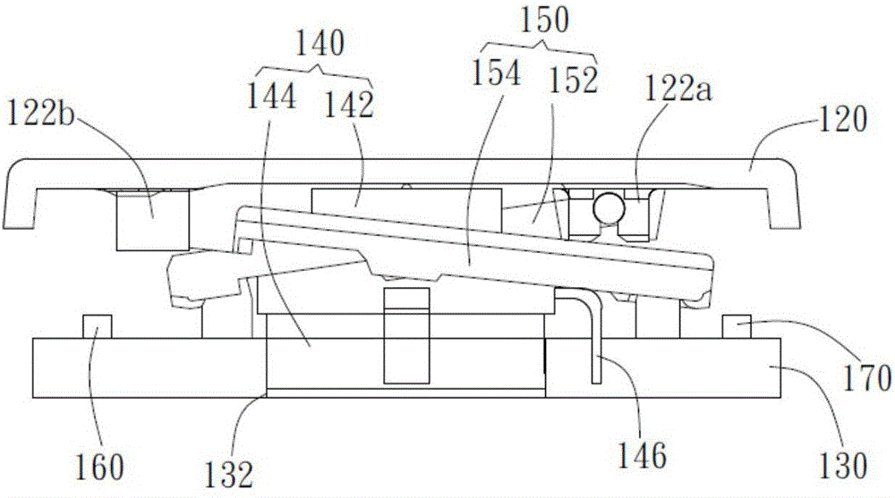
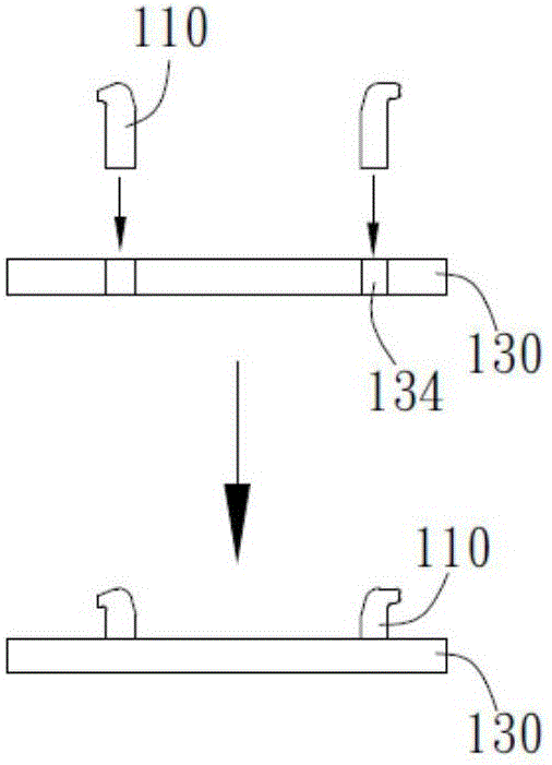
[0026] The present invention provides a button structure, which can be applied to any push-type input device, such as a keyboard, so as to improve the pressing feel, avoid the use of the bottom plate, and improve maintenance feasibility. The structure and operation of each element of the key structure according to the embodiment of the present invention will be d...


PUM


Abstract

The invention discloses a press key structure comprising a key cap, a rigid circuit board, at least one coupling member, a micro-switch and a support unit, wherein the key cap is provided with at least one connecting part, the rigid circuit board has an accommodating space, the at least one coupling member is arranged on the rigid circuit board and projects toward the key cap, the micro-switch is positioned below the key cap and is partially accommodated in the accommodating space, the micro-switch is electrically connected to the rigid circuit board, the support unit is coupled to the at least one connecting part and the at least one coupling member, and therefore the key cap can be supported to move relative to the rigid circuit board to trigger the micro-switch. According to the press key structure, through arrangement of the micro-switch, comfortable pressing touch can be realized, the micro-switch is integrated with the rigid circuit board which provides a needed electric path, and therefore feasibility and convenience of individual press key maintenance can be improved. According to the press key structure, the coupling member is integrated with the rigid circuit board, the circuit board is enabled to have a function of a coupling key cap or the supporting unit, no extra base plate is needed, and the number of elements of the press key structure is reduced.

Description

technical field [0001] The present invention relates to a key structure, in particular, the present invention relates to a key structure that improves the pressing feeling and eliminates the bottom plate. Background technique [0002] Conventional keyboard structures generally use thin film circuit layers as switching elements for signal generation. Generally speaking, the thin film circuit layer is composed of an upper circuit layer, a lower circuit layer and a spacer layer separating the upper and lower circuit layers, wherein the upper and lower circuit layers have a plurality of corresponding switch contacts as trigger circuits for a plurality of keys. When the keycap is pressed to trigger the membrane circuit layer, the upper circuit layer is deformed so that the switch contacts of the upper circuit layer contact the corresponding switch contacts of the lower circuit layer, and then the membrane switch is turned on to generate a signal. However, the thin film circuit l...

Claims


Application Information

Patent Timeline
Patent Type & Authority Applications(China)
IPC IPC(8): H01H13/705H01H3/12
CPCH01H13/705H01H3/125H01H2233/03
Inventor 张景川
Owner DARFON ELECTRONICS (SUZHOU) CO LTD
Learn More