Power adapter and electronic equipment suitable for the same
A technology for power adapters and electronic equipment, applied to electrical components, output power conversion devices, and conversion of AC power input to DC power output. The effect of system power-off, efficiency improvement, and circuit simplification
- Summary
- Abstract
- Description
- Claims
- Application Information
AI Technical Summary
Problems solved by technology
Method used
Image

Examples
no. 1 example
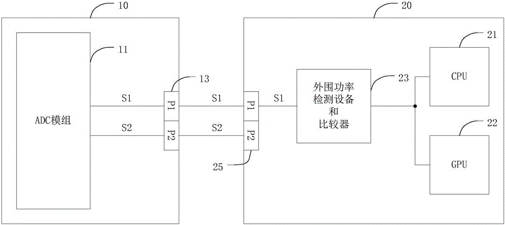
[0034] Such as figure 2 Shown is the structure and connection schematic diagram of the first embodiment of the power adapter and electronic equipment of the present invention. This example is for figure 1 The existing two-terminal power adapter and electronic equipment suitable for the power adapter are improved.
[0035] In this embodiment, the power adapter 10 includes an ADC module 11 , comparators C1 - C4 , a pull-high power supply VH1 , a pull-high resistor RH1 , and an output port 13 .
[0036] Among them, the output port 13 has three terminals P1, P2, and P3. The terminal P1 is used to output the DC signal S1, the terminal P2 is used to output the ground signal S2 of the adapter, and the newly added terminal P3 is used to output the early warning signal S3. Although figure 2 The newly added terminal P3 shown in FIG.
[0037] The first input terminals of the comparators C1-C4 are connected to the ADC module 11, which are respectively used to receive the DC voltage...
no. 2 example
[0048] Such as Figure 4 Shown is the structure and connection schematic diagram of the second embodiment of the power adapter and electronic equipment of the present invention. This example is for image 3 The existing three-terminal power adapter and electronic equipment suitable for the power adapter are improved.
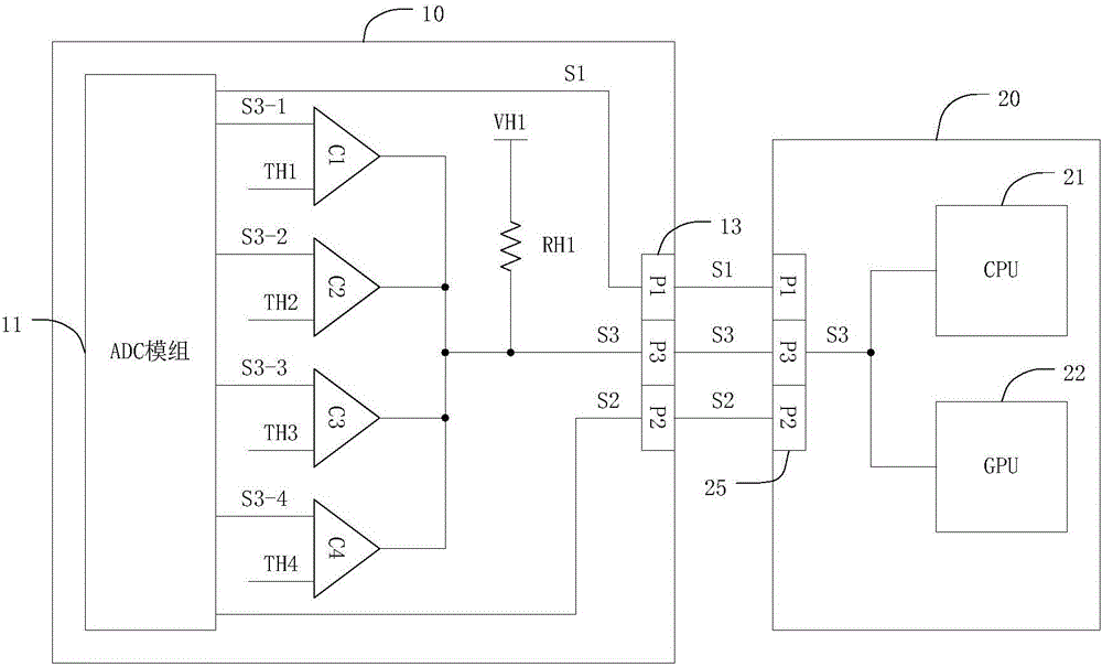
[0049] Three-terminal power adapter and applicable electronic equipment in the prior art such as image 3 shown. The output port 13 of the power adapter 10 includes three terminals P1-P3, which are respectively used to output a DC signal S1, a ground signal S2 of the adapter, and a power identification signal S3'. Wherein, the power identification signal S3' is used for the motherboard 20 to identify the power of the power adapter 10.
[0050] Such as image 3 As shown, the power adapter 10 also includes a pull-down resistor RL, and the terminal P3 of the output port 13 is grounded through the pull-down resistor RL. The main board 20 is also provided with ...
no. 3 example
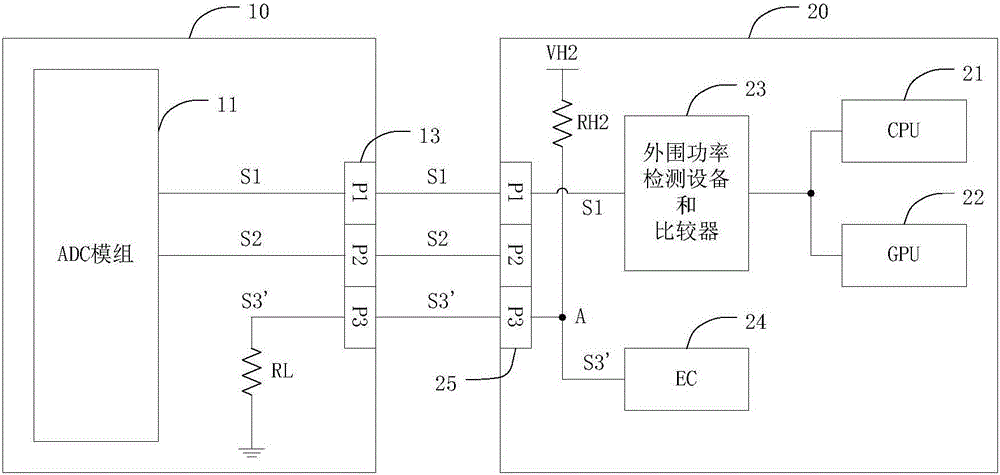
[0073] The structure diagram of this embodiment is as Figure 5 As shown, it is based on the premise of ensuring functional integrity Figure 4 further simplification. As can be seen from the circuit structure, the circuit structure of the present embodiment, the improved prior art ( image 3 ) change ratio Figure 4 Smaller and easier to implement.
[0074] Compared with the second embodiment, this embodiment omits the second embodiment ( Figure 4 ), the first pull-up power supply VH1 in the power adapter 10 , the first pull-up resistor RH1 , the second control switch K2 , and the third control switch K3 on the motherboard 20 . The specific structure is as Figure 5 As shown, since the structure is basically the same as that of the second embodiment, it will not be described again.
[0075] When the power adapter 10 is connected to the main board 20, the charger will send the adapter insertion signal S4 to the EC24, and the EC24 immediately starts the power detection p...
PUM
 Abstract
Description
Claims
Application Information
 - R&D
- Intellectual Property
- Life Sciences
- Materials
- Tech Scout
- Unparalleled Data Quality
- Higher Quality Content
- 60% Fewer Hallucinations
Browse by: Latest US Patents, China's latest patents, Technical Efficacy Thesaurus, Application Domain, Technology Topic, Popular Technical Reports.
© 2025 PatSnap. All rights reserved.Legal|Privacy policy|Modern Slavery Act Transparency Statement|Sitemap|About US| Contact US: help@patsnap.com