Switch power source and bus capacitor voltage control method used for switch power source

A bus capacitor and switching power supply technology, which is applied in the field of switching power supplies, can solve the problems that the bus capacitor cannot be miniaturized and the proportion of the bus capacitor is increasing, so as to shorten the discharge time, realize the miniaturization, and reduce the capacitance value.

Active Publication Date: 2016-07-13
DELTA ELECTRONICS INC
View PDF8 Cites 16 Cited by
  • Summary
  • Abstract
  • Description
  • Claims
  • Application Information

AI Technical Summary

Problems solved by technology

The function of the bus capacitor in the switching power supply is to balance the instantaneous input and output power, so the bus capacitor cannot be miniaturized with the high frequency. As a result, the proportion of the bus capacitor volume in the switching power supply increases with the high frequency. The bigger it becomes, the bottleneck of the miniaturization of the switching power supply

Method used


Image

  • Switch power source and bus capacitor voltage control method used for switch power source
  • Switch power source and bus capacitor voltage control method used for switch power source
  • Switch power source and bus capacitor voltage control method used for switch power source

Examples


Embodiment Construction

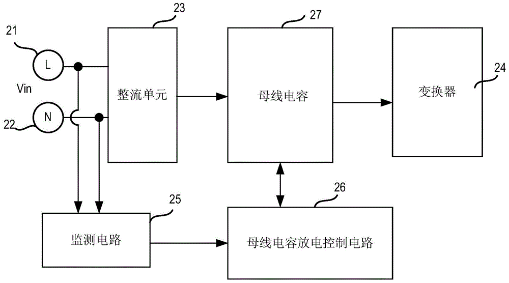
[0025] figure 2 A circuit block diagram of an embodiment of the switching power supply of the present application is schematically shown, and the switching power supply includes: a rectifying unit 23 , a bus capacitor 27 , a converter 24 , a monitoring circuit 25 and a bus capacitor discharge control circuit 26 .

[0026] The rectification unit 23 includes an AC side and a DC side, and the rectification unit 23 is configured to convert the AC voltage input from the AC side into a DC voltage output from the DC side. The AC side includes a first AC voltage input terminal 21 and a second AC voltage input terminal 22, and these two input terminals are used for receiving an input AC voltage Vin. For example, one of the first AC voltage input terminal 21 and the second AC voltage input terminal may be connected to the neutral line (N), and the other may be connected to the live line (L). The rectification unit 23 may be, for example, a rectification element such as a rectification...


PUM


Abstract

The invention provides a switch power source and a bus capacitor voltage control method used for the switch power source. The switch power source includes a rectification unit provided with a DC side and an AC side and used for converting input AC voltage to DC voltage; a bus capacitor; a converter; a monitoring circuit used for detecting whether and judging whether the instant absolute value of the DC voltage is greater than a predetermined voltage; a bus capacitor discharge control circuit used for controlling when the instant absolute value of the DC voltage is greater than predetermined voltage so as to enable the bus capacitor to be charged by the rectification unit to the peak value of the AC voltage and to keep peak value, and controlling the bus capacitor to discharge from the peak value of the AC voltage so as to provide energy to the converter when the instant absolute value of the DC voltage is smaller or equal to predetermined voltage. By adopting the technical scheme provided by the invention, the discharge time of the bus capacitor is reduced and the size of the bus capacitor is reduced, so that the mini size of the switch power source is realized.

Description

technical field [0001] The present application relates to the field of switching power supplies, in particular to a switching power supply with reduced bus capacitance and a bus capacitance voltage control method for the switching power supply. Background technique [0002] figure 1 Schematically shows a circuit block diagram of a known switching power supply, the bus capacitor C_bulk in the switching power supply is connected in parallel with the rectifier bridge 11 and the converter 12 of the subsequent stage, and the bus capacitor C_bulk can be rectified by the voltage rectified by the rectifier bridge 11 Charging can also supply energy to the converter 12 of the subsequent stage. [0003] In recent years, switching power supplies tend to develop in the direction of miniaturization. In order to adapt to this development trend, the switching power supply tends to increase in frequency, and the volume of the magnetic components in the switching power supply (for example, ...

Claims


Application Information

Patent Timeline
Patent Type & Authority Applications(China)
IPC IPC(8): H02M7/04H02M1/00
CPCH02M1/15H02M3/335H02M7/06H02M1/007H02M3/33507
Inventor 宋海斌许道飞
Owner DELTA ELECTRONICS INC
Why Eureka
Try Eureka