Check patentability & draft patents in minutes with Patsnap Eureka AI!

telecentric lens

A telecentric lens and lens technology, applied in instruments, measuring devices, optics, etc., can solve problems such as complex manufacturing, difficulty in obtaining optimal alignment of lens components, and high cost

Active Publication Date: 2018-09-25
OPTO ENG SPA
View PDF8 Cites 0 Cited by
  • Summary
  • Abstract
  • Description
  • Claims
  • Application Information

AI Technical Summary

Problems solved by technology

[0007] The complexity of making such negative lenses 30 and 32, combined with the type of shape required and the overall number of optical components required to make the telecentric lens, complicates its manufacture, in addition to high cost, because these configurations factors that make it more difficult to obtain optimal alignment of the lens assembly

Method used


Image

  • telecentric lens
  • telecentric lens
  • telecentric lens

Examples


Embodiment Construction

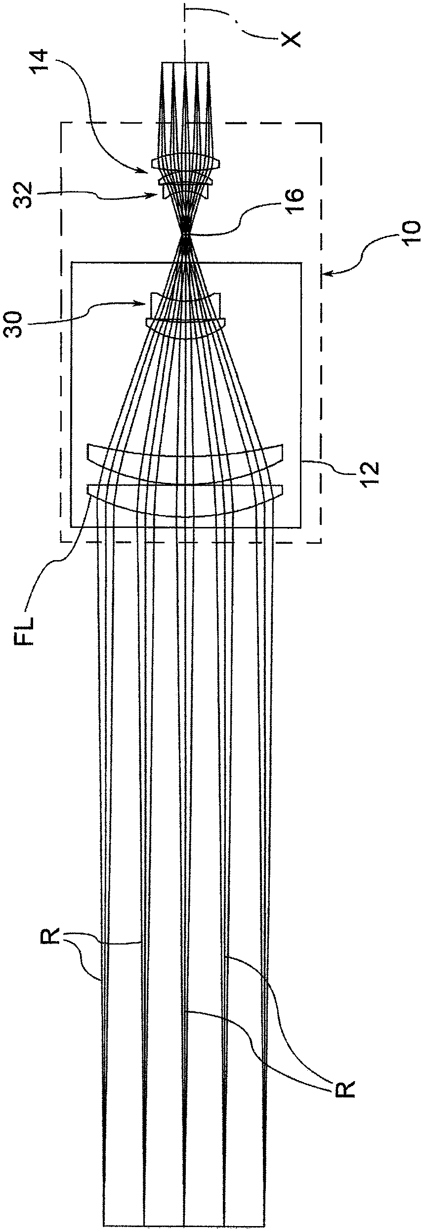
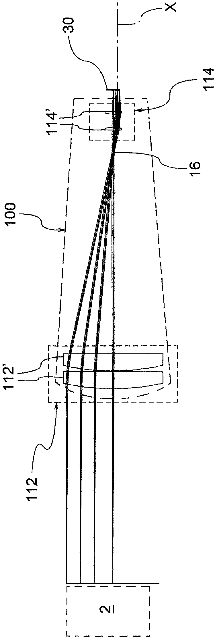
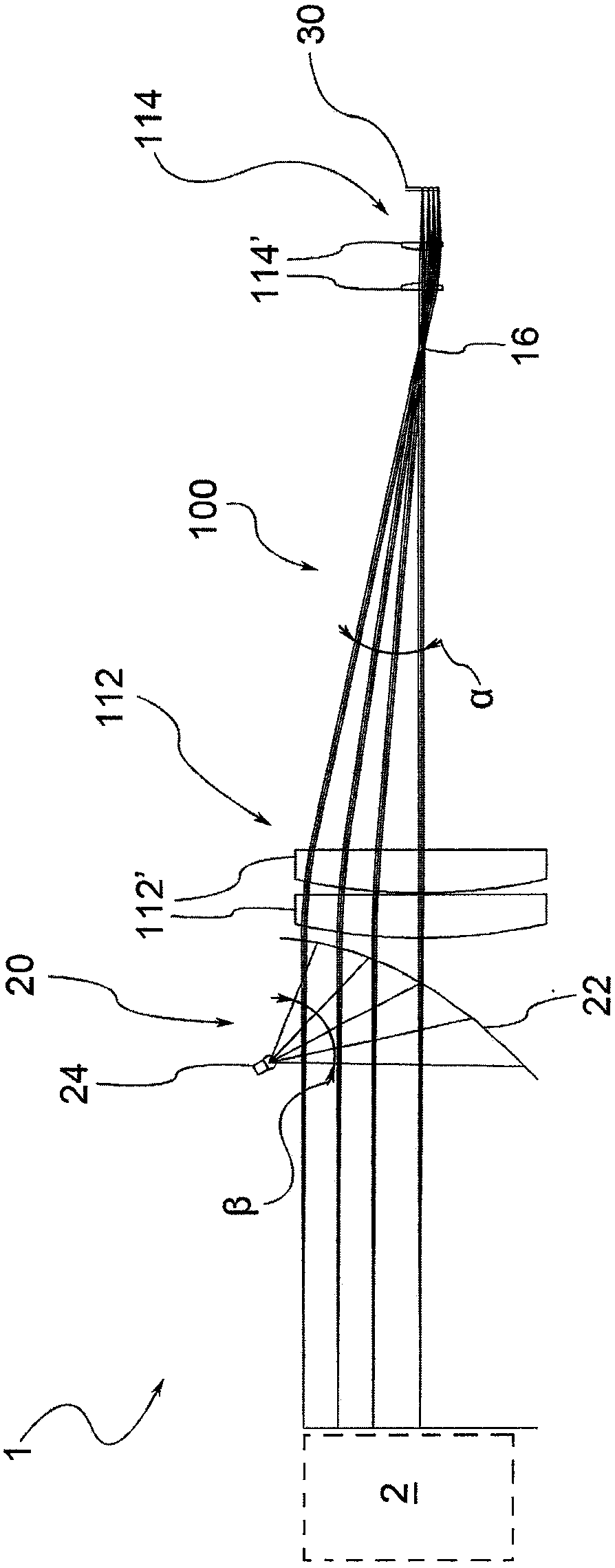
[0014] refer to figure 2 , the telecentric lens 100 according to the invention has a principal optomechanical axis X and comprises a front optical group 112 adapted to receive rays from the object 2 to be observed and a front optical group 112 adapted to transmit said rays to the sensor 30 of the vision device Rear optical group 114 . A telecentric lens aperture (indicated by reference numeral 16 ) is located between the front optical group 112 and the rear optical group 114 .

[0015] The front optical group 112 is intended to collect the rays from the object 2 in such a way that the axis of each ray cone is parallel to the chief beam by virtue of the position of the aperture 16 itself in the focal plane of the front optical group 112 Mechanical axis X. On the other hand, the rear optical group 114 collects the radiation passing through the aperture 16 and focuses the radiation on the sensor 30 to allow image formation. According to a preferred embodiment of this optical ...


PUM


Abstract

A method and a device for the optical viewing of objects, the method comprising the stages of illuminating an object with ultraviolet radiation, and acquiring an image of the object thereby illuminated using a lens comprising at least a forward optical group and an aperture diaphragm exhibiting a transparent window located at a focal point of the forward optical group defined for the ultraviolet radiation.

Description

technical field [0001] The invention relates to a telecentric lens for use in a device for artificial vision, in particular for performing dimensional measurements of objects. Background technique [0002] It is well known that artificial vision typically uses telecentric lenses for dimensional measurement applications. figure 1 An optical diagram of a telecentric lens according to the prior art is shown. [0003] The telecentric lens 10 has a main opto-mechanical axis X and comprises a front optical group 12 adapted to receive rays from an object to be viewed and a front optical group 12 adapted to transmit said rays to a sensor of a vision device. Rear optical group 14. Telecentric lens 10 differs from conventional, or "entocentric" lenses in that a telecentric lens receives only the center of the gravity ray (or principal ray) from the object being A cone of rays R parallel to the axis X. To this end, the telecentric lens must have a front lens FL at least as wide as ...

Claims


Application Information

Patent Timeline
Patent Type & Authority Patents(China)
IPC IPC(8): G01B11/02G02B13/22
Inventor 克劳迪奥·塞达扎里
Owner OPTO ENG SPA
Features
  • R&D
  • Intellectual Property
  • Life Sciences
  • Materials
  • Tech Scout
  • Unparalleled Data Quality
  • Higher Quality Content
  • 60% Fewer Hallucinations
Learn More