In-situ detecting equipment for abrasion on rear face of turning tool

A technology for turning tools and testing equipment, which is applied in the direction of measuring/indicating equipment, metal processing equipment, manufacturing tools, etc. It can solve problems such as lens distortion correction, achieve small size, high precision requirements, and ensure the effect of phase quality

Active Publication Date: 2016-02-24
HUAZHONG UNIV OF SCI & TECH
View PDF6 Cites 20 Cited by
  • Summary
  • Abstract
  • Description
  • Claims
  • Application Information

AI Technical Summary

Problems solved by technology

[0005] Aiming at the above defects or improvement needs of the prior art, the present invention provides an in-situ detection device for flank wear of a turning tool, in which the distortion correction problem of commonly used lenses is solved by adopting a telecentric lens, and by adopting a small field of view Combination of camera and lens, combined with coaxial light illumination, solves the influence of light source on imaging quality in traditional methods, and designs a flexible multi-degree-of-freedom adjustment device. Through reasonable installation and arrangement, the alignment between lens and imaging plane is realized. Precise vertical positioning ensures the image quality of the image

Method used


Image

  • In-situ detecting equipment for abrasion on rear face of turning tool
  • In-situ detecting equipment for abrasion on rear face of turning tool
  • In-situ detecting equipment for abrasion on rear face of turning tool

Examples


Embodiment Construction

[0025] In order to make the object, technical solution and advantages of the present invention clearer, the present invention will be further described in detail below in conjunction with the accompanying drawings and embodiments. It should be understood that the specific embodiments described here are only used to explain the present invention, not to limit the present invention. In addition, the technical features involved in the various embodiments of the present invention described below can be combined with each other as long as they do not constitute a conflict with each other.

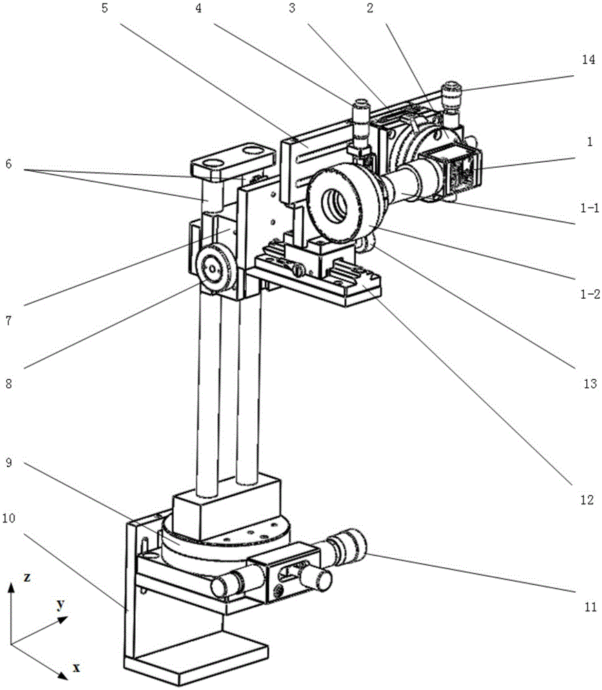
[0026] Such as figure 1 As shown, an in-situ detection device for flank wear of a turning tool according to the present invention mainly includes an imaging device and a pose adjustment device. Use the imaging device to take high-precision photos of the flank wear area of ​​the turning tool, and the image resolution can reach more than 400pixel / mm. Obtain the wear condition of the tool flank ac...


PUM


Abstract

The invention discloses in-situ detecting equipment for abrasion on the rear face of a turning tool. The in-situ detecting equipment comprises an imaging device and a pose and position adjusting device, wherein the imaging device comprises a camera, a telecentric lens and coaxial light sources, the telecentric lens is mounted on the camera, and the coaxial light sources are fixed at the tail end of the telecentric lens; the pixel of the camera is not lower than 200w, and the chip of the camera is not smaller than 1 / 1.8 inch in size; the distortion factor of the telecentric lens is not higher than 0.02 percent; the image resolution of the combination of the camera and the telecentric lens is not lower than 400 pixel / mm, and the entire length is not longer than 150 mm; and the pose and position adjusting device is used for achieving multi-degree-of-freedom precision adjustment of the imaging device. During the work, the imaging device is fixed on one side, positioned on the outer normal of the rear face of the turning tool, of a lathe lateral displacement planker through the pose and position adjusting device. The in-situ detecting equipment provided by the invention has the advantages of high measuring accuracy, convenience in measurement and the like, and is applicable to abrasion on the rear face of the turning tool.

Description

technical field [0001] The invention belongs to the field of tool wear monitoring, and more specifically relates to an in-situ detection device for flank wear of a turning tool. Background technique [0002] The turning tool is the main forming tool in turning, and the wear and damage of the tool are the main factors affecting the cutting quality. After the tool is worn, the machining accuracy of the workpiece is reduced, the surface integrity is deteriorated, and the cutting force is further increased and the cutting temperature is increased, which further reduces the tool life and directly affects the processing cost and processing efficiency. With the automation, high speed and intelligence of the machining process, the detection of the working state of the tool has become an important part of the monitoring of the modern turning process. [0003] The wear type of the turning tool can be divided into flank wear, crater wear, chipping, crushing and other forms according t...

Claims


Application Information

Patent Timeline
Patent Type & Authority Applications(China)
IPC IPC(8): B23Q17/09B23Q17/24
CPCB23Q17/0957B23Q17/2409B23Q17/2457
Inventor 张云付洋黄志高周华民李德群杨志明
Owner HUAZHONG UNIV OF SCI & TECH
Why Eureka
Try Eureka