
Cotton stalk pulling mechanism

A technology for pulling out cotton stalks and cotton stalks, which is applied in the field of cotton stalk pulling devices, which can solve problems such as difficult cutting, grass entanglement, and high energy consumption, and achieve the effect of simplifying the structure and preventing the blades from tangling grass

Active Publication Date: 2016-07-20
NANJING AGRI MECHANIZATION INST MIN OF AGRI
View PDF10 Cites 4 Cited by
  • Summary
  • Abstract
  • Description
  • Claims
  • Application Information

AI Technical Summary

Problems solved by technology

According to the applicant's understanding, the cotton stalks in the cotton area of ​​the Yangtze River Basin in my country are difficult to cut because of their thick stalks. Now, double-toothed disc-type cotton stalk pullers are commonly used. This kind of cotton stalk puller has higher requirements for the operator and requires Accurate row harvesting, the efficiency of pulling cotton stalks is difficult to further improve
There are also areas that use the four-edged knife-style method of pulling out cotton stalks. This method requires four-edged knives to work in the soil and consumes a lot of energy; Research institutes such as the institute have all developed a horizontal roller type V-shaped tooth misaligned cotton stalk pulling mechanism. This cotton stalk pulling mechanism has improved the clamping force on the cotton stalk, so it can also achieve good results without entering the soil. Cotton stalk mechanisms have the problem of entanglement (cotton stalk husk) during use, and often require additional grass cleaning devices to work properly

Method used


Image

  • Cotton stalk pulling mechanism
  • Cotton stalk pulling mechanism
  • Cotton stalk pulling mechanism

Examples


Embodiment

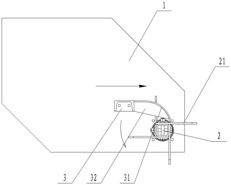
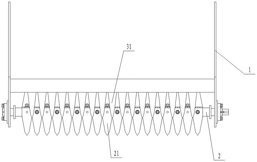
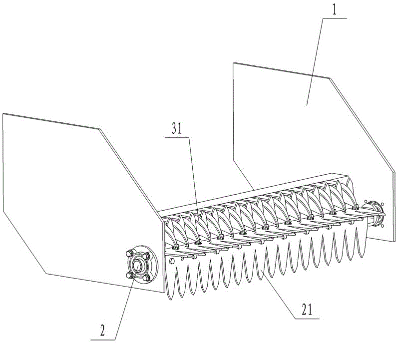
[0018] The mechanism for pulling out cotton stalks in this embodiment, such as figure 1 , figure 2 and image 3 As shown, it includes the stalk pulling tooth roller shaft 2 arranged on the frame 1 and the stalk retracting tooth seat 3 fixed on the frame 1. The stalk tooth roller shafts are arranged relative to each other. The stalk puller teeth 21 are fixed on the stalk puller tooth roller shaft 2, and a plurality of stalk puller teeth 31 are fixed on the stalk puller tooth seat 3. Between two adjacent stalk puller teeth 31 V-shaped notches are formed. Reinforcing ribs 32 are fixed on the stalk teeth 31 .

[0019] Each stalk-removing tooth 31 is an arc-shaped tooth protruding forward and downward, the outer circular surface of the arc-shaped tooth protrudes forward and upward, and the front end of the stalk-removing tooth 31 protrudes from the forward and downward position to pass over the stalk pulling tooth roller Axis 2 centerline.

[0020] When the stalk tooth roller...


PUM


Abstract

The invention relates to a cotton stalk pulling mechanism and belongs to the technical field of agricultural machinery.The cotton stalk pulling mechanism comprises a pulling tooth roller shaft and a retreating tooth holder arranged on a frame, the retreating tooth holder is arranged above the rear of the pulling tooth roller shaft, pulling teeth are fixed on the pulling tooth roller shaft, a plurality of retreating teeth are fixed on the retreating tooth holder, a V-shaped gap forms between every adjacent two of the retreating teeth, each retreating tooth is an arc tooth extending forward down, and an outer arc surface of each arc tooth protrudes forward up; when the pulling tooth roller shaft rotates, a segment of each pulling tooth is rotated into the corresponding V-shaped gap, two sides of this segment are kept 2-5 mm away from two sides of the V-shaped gap constantly, and when the pulling tooth roller shaft drives the pulling teeth to rotate and pull out cotton stalks, the pulling teeth push the cotton stalks backwardly along the outer arc surfaces of the retreating teeth.The cotton stalk pulling mechanism has the advantage that the mechanism can automatically prevent entwining of weeds and cotton stalk peel and operate normally without additional cleaning devices.

Description

technical field [0001] The invention relates to a cotton stalk pulling device, which belongs to the technical field of agricultural machinery. Background technique [0002] my country is a big country of cotton production. Cotton stalk resources are very rich. It is an important renewable biomass resource. With the improvement of my country's economic level and industrial technology, it is used as a biomass raw material in various industries. The cotton stalk The available value is getting higher and higher. Therefore, improving the harvest rate of cotton stalks and realizing the resource and commercialization of cotton stalks is of great significance to promote national energy development, environmental protection and economic level. [0003] The performance of the existing cotton stalk harvesting equipment depends on the performance of the cotton stalk pulling mechanism. As far as the applicant knows, the cotton stalks in the cotton area of ​​the Yangtze River Basin in my...

Claims


Application Information

Patent Timeline
Patent Type & Authority Applications(China)
IPC IPC(8): A01D45/00
CPCA01D45/00
Inventor 陈明江王振伟曲浩丽陈永生韩柏和
Owner NANJING AGRI MECHANIZATION INST MIN OF AGRI
Learn More