Method and device for integrally removing multiple pollutants in tail gas through plant ash seriflux

A technology for plant ash and pollutants, applied in chemical instruments and methods, gas treatment, separation methods, etc., can solve problems such as endangering the health of the ecological environment, generating solid waste, and limited secondary utilization.

Active Publication Date: 2016-07-20
刘杨先
View PDF5 Cites 10 Cited by
  • Summary
  • Abstract
  • Description
  • Claims
  • Application Information

AI Technical Summary

Problems solved by technology

Due to the limited secondary utilization of plant ash, a large amount of solid waste is generated in t

Method used


Image

  • Method and device for integrally removing multiple pollutants in tail gas through plant ash seriflux
  • Method and device for integrally removing multiple pollutants in tail gas through plant ash seriflux
  • Method and device for integrally removing multiple pollutants in tail gas through plant ash seriflux

Examples


Embodiment 1

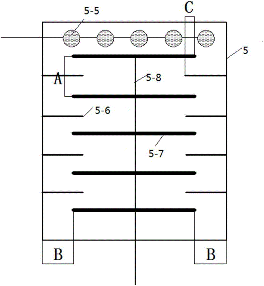
[0068] Example 1. SO in flue gas 2 , NO x , Hg, H 2 The concentrations of S, HCl, and HF are respectively 5000ppm, 500ppm, and 80ug / m 3 , 3000ppm, 1000ppm and 1000ppm, flue gas temperature is 45°C, liquid-gas ratio is 5L / m 3 , the mass concentration of plant ash slurry is 100g / L, and the longitudinal distance A between the ultraviolet lamp tubes is located at 10cm. The distance B between the top of the ultraviolet lamp tube and the reactor wall is 1 cm, and the overlapping length of the ultraviolet lamp tube and the guide plate is between 2 cm. The guide plate is arranged at the center of the longitudinal distance between two adjacent ultraviolet lamp tubes. The solution atomization diameter of the nozzle is 150 microns. The rotation speed of the rotating paddle is 20 rpm. SO in flue gas 2 , NO x , Hg, H 2 The simultaneous removal efficiencies of S, HCl and HF were 59.3%, 15.9%, 28.9%, 48.8%, 58.8% and 48.2%, respectively.

Embodiment 2

[0069] Example 2. SO in flue gas 2 , NO x , Hg, H 2 The concentrations of S, HCl, and HF are respectively 5000ppm, 500ppm, and 80ug / m 3 , 3000ppm, 1000ppm and 1000ppm, flue gas temperature is 45°C, liquid-gas ratio is 8L / m 3 , the mass concentration of plant ash slurry is 100g / L, and the longitudinal distance A between the ultraviolet lamp tubes is located at 10cm. The distance B between the top of the ultraviolet lamp tube and the reactor wall is 1 cm, and the overlapping length of the ultraviolet lamp tube and the guide plate is between 2 cm. The guide plate is arranged at the center of the longitudinal distance between two adjacent ultraviolet lamp tubes. The solution atomization diameter of the nozzle is 150 microns. The rotation speed of the rotating paddle is 20 rpm. SO in flue gas 2 , NO x , Hg, H 2 The simultaneous removal efficiencies of S, HCl and HF were 78.3%, 24.9%, 30.9%, 69.3%, 78.8% and 68.7%, respectively.

Embodiment 3

[0070] Example 3. SO in flue gas 2 , NO x , Hg, H 2 The concentrations of S, HCl, and HF are respectively 5000ppm, 500ppm, and 80ug / m 3 , 3000ppm, 1000ppm and 1000ppm, the flue gas temperature is 45°C, the molar concentration of hydrogen peroxide is 0.08mol / L, the ozone injection concentration is 30ppm, and the liquid-gas ratio is 5L / m 3 , the mass concentration of plant ash slurry is 100g / L, and the longitudinal distance A between the ultraviolet lamp tubes is located at 10cm. The distance B between the top of the ultraviolet lamp tube and the reactor wall is 1 cm, and the overlapping length of the ultraviolet lamp tube and the guide plate is between 2 cm. The guide plate is arranged at the center of the longitudinal distance between two adjacent ultraviolet lamp tubes. The solution atomization diameter of the nozzle is 150 microns. The rotation speed of the rotating paddle is 20 rpm. SO in flue gas 2 , NO x , Hg, H 2 The simultaneous removal efficiencies of S, HCl a...


PUM


Abstract

The invention relates to a method and device for integrally removing multiple pollutants in tail gas through plant ash seriflux. The method comprises the steps that plant ash seriflux is adopted for independently or jointly oxidize and remove SO2, NOx, Hg, H2S, HCl and HF in tail gas of a combustion or chemical device; tail gas containing SO2, NOx, Hg, H2S, HCl and HF from a boiler or kiln or chemical device is cooled and enters a rotary absorption reactor; soluble or acid gas SO2, NO2, Hg2+, H2S, HCl and HF can be directly washed and absorbed by a solution, and indissolvable gas NO and Hg0 can be absorbed by a solution after being pre-oxidized or oxidized by an additive into NO2, HNO2, HNO3 and Hg2+. According to the method, resource utilization can be achieved for solid waste produced by biomass burning, multiple pollutants can be integrally removed, the purpose of dealing with waste by waste is achieved, secondary pollution is avoided in the whole removal process, and the market development and application prospect is wide.

Description

technical field [0001] The invention relates to the control of flue gas emission pollutants in the combustion process, in particular to a plant ash slurry for the multi-pollutant SO in the tail gas produced by boilers, kilns or industrial devices. 2 ﹑NO x ﹑Hg﹑H 2 An integrated removal method and device for S, HCl, and HF. Background technique [0002] SO from combustion process and chemical tail gas 2 ﹑NO x ﹑Hg﹑H 2 S, HCl, and HF can cause acid rain, photochemical smog, equipment corrosion, carcinogenicity, and teratogenicity, which seriously endanger human health and the ecological environment. Therefore, the development of cost-effective SO in tail gas 2 ﹑NO x ﹑Hg﹑H 2 S﹑HCl﹑HF removal technology is one of the important tasks of environmental protection scientists and technicians all over the world. In recent years, although people have developed a large amount of exhaust SO 2 ﹑NO x ﹑Hg﹑H 2 S﹑HCl﹑HF removal technology, but due to the limitations of human cogniti...

Claims


Application Information

Patent Timeline
IPC IPC(8): B01D53/78B01D53/60B01D53/64B01D53/52B01D53/68
CPCB01D53/52B01D53/60B01D53/64B01D53/68B01D53/78B01D2251/10B01D2258/0283Y02A50/20
Inventor 刘杨先
Owner 刘杨先
Why Eureka
Try Eureka