A heat retaining test tube stand

A test tube rack and electric heating tube technology, which is applied in the directions of test tube supports/clamps, heating or cooling equipment, laboratory utensils, etc.

Inactive Publication Date: 2016-07-20
TIANJIN LIYOU MACHINERY MFG CO LTD
View PDF0 Cites 2 Cited by
  • Summary
  • Abstract
  • Description
  • Claims
  • Application Information

AI Technical Summary

Problems solved by technology

[0003] What the invention creates is to solve the problem that the test tube rack cannot keep the heat for the test tube

Method used


Image

  • A heat retaining test tube stand

Examples


Embodiment Construction

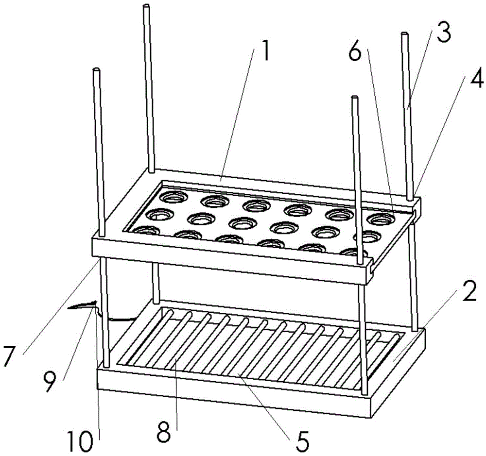
[0014] An insulated test tube rack, comprising a support plate 1 and a bottom plate 2;

[0015] The four corners of the bottom plate 2 are respectively fixedly connected with four guide columns 3;

[0016] The four corners of the support plate 1 are respectively provided with guide holes 4, and are fixedly sleeved on the guide columns 3 through the guide holes 4;

[0017] A number of through holes 6 are provided on the support plate 1 for placing test tubes;

[0018] There is a square groove 5 on the plate surface of the base plate 2, and several heating pipes 8 are evenly arranged inside the square groove 5, and the heating pipes 8 are connected with the air circulation pipe inside the base plate 2, and the circuit board is connected to the air circulation pipe inside the base plate 2. The air circulation pipe is connected with the air circulation pipe, and the heat energy converted from the electric energy is transferred to the electric heating pipe 8 by the air circulation...


PUM


Abstract

The invention provides a heat retaining test tube stand. The test tube stand comprises a supporting plate and a base plate. The four corners of the base plate are respectively fixedly connected to four guide columns. Lower ends of the guide columns are provided with screws. The four corners of the supporting plate are respectively provided with guide holes and sleeve the guide columns through the guide holes. In lower part of the supporting plate, the guide columns are sleeved with nuts matched with the screws on the guide columns. The supporting plate is provided with a plurality of though holes for accommodating test tubes. The surface of the base plate is provided with a square groove. A plurality of heating tubes are evenly disposed in the square groove, and are communicated with air flowing pipes inside the base plate. A circuit board is communicated with the air flowing pipes. The air flowing pipes transfer heat converted from electricity to the heating tubes. The test tube stand is provided with heating and heat retaining devices and allows agents in the test tubes to be at the most proper temperature by virtue of electricity, thus ensuring success performing of experiments, and simplifying experiment devices. The test tube stand has practical application value.

Description

technical field [0001] The invention relates to the field of biological equipment, in particular to an insulated test tube rack. Background technique [0002] At present, in the process of separating and preparing various stem cells from various tissue sources, test tubes with a capacity of 15ml and 50ml are one of the low-value consumables with a high usage rate. When it is taken out by the operator, it is placed on the plastic test tube rack in the ultra-clean workbench. It is well known that many proteases work best at a certain temperature, and many sample reagents need to be stored at a specific temperature when performing experiments. In the prior art, the experimental operator usually places the test tube together with the test tube rack in the heat preservation device to keep the temperature in the test tube. The temperature required by the reagent is very inconvenient to operate. Contents of the invention [0003] The invention aims to solve the problem that the...

Claims


Application Information

Patent Timeline
Patent Type & Authority Applications(China)
IPC IPC(8): B01L9/06B01L7/00
Inventor 南长海
Owner TIANJIN LIYOU MACHINERY MFG CO LTD
Why Eureka
Try Eureka