
A CNC lathe with a vacuum suction cup

A technology of CNC lathes and vacuum suction cups, which is applied in the directions of manufacturing tools, clamping, and supporting, and can solve the problems of difficult processing, difficult to fix and clamp, etc.

Active Publication Date: 2018-05-25
中山市北村机械设备有限公司
View PDF8 Cites 0 Cited by
  • Summary
  • Abstract
  • Description
  • Claims
  • Application Information

AI Technical Summary

Problems solved by technology

[0002] Existing lathes are difficult to fix and clamp when processing thin-sheet products, resulting in difficult processing. Therefore, the present invention provides a numerically controlled lathe for thin-sheet products to solve the above problems

Method used


Image

  • A CNC lathe with a vacuum suction cup

Examples


Embodiment Construction

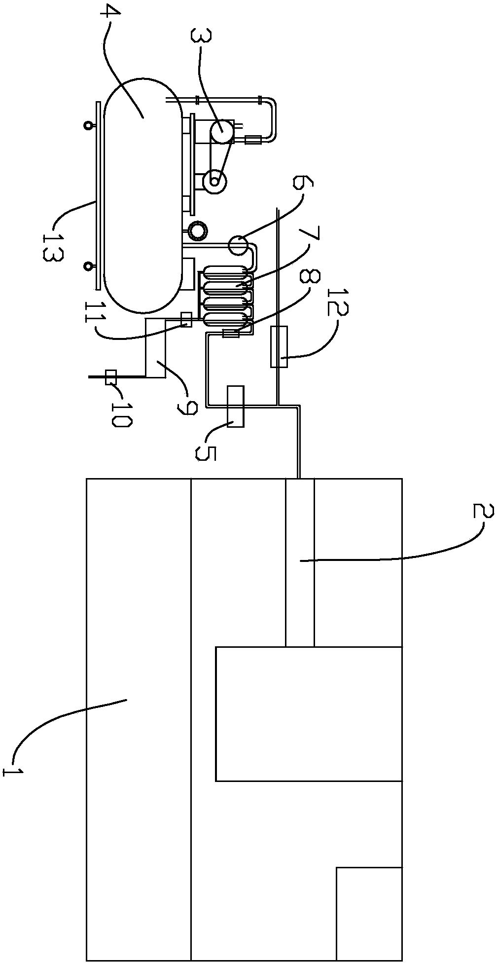
[0012] refer to figure 1 , the present invention is a kind of numerically controlled lathe with vacuum sucker, comprises frame 1 and vacuum generating device, and frame 1 is provided with main shaft 2, and the front end of main shaft 2 is provided with a suction plate, and the suction plate has a flat surface, and this suction A number of ventilation holes are arranged on the material plate, and the vacuum generating device communicates with the ventilation holes. The present invention adopting the above structure is provided with a suction plate on the main shaft 2, and a vent hole is arranged on the suction plate, and the through hole is vacuumed by a vacuum generating device, and then the sheet-type product is sucked. It can be seen that the present invention with the above structure can Thin sheet products have the effect of fixed clamping.

[0013] Such as figure 1 As shown, the vacuum generating device can specifically adopt the following embodiments, including a vacuu...


PUM


Abstract

The invention discloses a numerically-controlled lathe with a vacuum suction disc. The numerically-controlled lathe with the vacuum suction disc comprises a rack and a vacuum generation device, wherein a main shaft is arranged on the rack; a material absorption plate is arranged at the front end of the main shaft; a plurality of vent holes are arranged in the material absorption plate; and the vacuum generation device communicates with the vent holes. According to the numerically-controlled lathe with the vacuum suction disc, which adopts the abovementioned structure, the material absorption plate is arranged on the main shaft, the vent holes are arranged in the material absorption plate and are vacuumized through the vacuum generation device, and then sheet products are absorbed; therefore, a fixed clamping effect can be acted on the sheet products.

Description

technical field [0001] The invention relates to a numerically controlled lathe with a vacuum suction cup. Background technique [0002] It is difficult for existing lathes to perform fixed clamping when processing thin-sheet products, resulting in difficulty in processing. Therefore, the present invention provides a numerically controlled lathe for thin-sheet products to solve the above problems. Contents of the invention [0003] In order to solve the above problems, the present invention provides a numerically controlled lathe with a vacuum suction cup. [0004] The technical solution adopted by the present invention to solve its technical problems is: [0005] A numerically controlled lathe with a vacuum suction cup, comprising a frame and a vacuum generating device, the frame is provided with a main shaft, the front end of the main shaft is provided with a suction plate, the suction plate is provided with a number of air holes, the vacuum generating The device commun...

Claims


Application Information

Patent Timeline
Patent Type & Authority Patents(China)
IPC IPC(8): B23Q3/12F04B41/02F04B37/14F04B39/16
CPCB23Q3/12B23Q2703/04F04B37/14F04B39/16F04B41/02
Inventor 宋静钟加金宋月
Owner 中山市北村机械设备有限公司
Learn More