
A clamping device for financial bills

A clamping device, a technology for financial bills, applied in binding, printing and other directions, can solve the problems of clamping, easy loss, low efficiency, etc., and achieve the effect of convenient operation

Active Publication Date: 2022-05-10
陈子越
View PDF6 Cites 1 Cited by
  • Summary
  • Abstract
  • Description
  • Claims
  • Application Information

AI Technical Summary

Problems solved by technology

[0002] In financial management, financial bills are an important bill certificate, which is not only related to individuals, but also to companies, so it is necessary to pay great attention to the storage of financial bills, but at present most financial bills are placed in the bill box, which makes Inconvenient to use, every time you use it, you need to open the bill box and then take it out, which reduces the work efficiency, so a financial bill holding device is needed
[0003] Existing patent CN211335280U discloses a kind of bill clamping device for accounting which is convenient for sorting bills. The six clampers forming regular hexagons arranged on the bottom plate classify and clamp different kinds of bills. However, in the existing device, at least There are also the following technical problems: 1) the existing clamping device is inconvenient to take, and can not be adjusted and clamped according to the number of bills of different thicknesses. When too much, the effect of fixed clamping cannot be achieved. 2) In the existing devices, sharp clamping parts such as iron clips are usually used to clamp the bills, which is easy to cause damage to the bill paper, such as wrinkles, piercing, etc.; 3) The existing devices There are many parts (such as springs, nuts, etc.) and they can be disassembled directly, so they are easy to lose

Method used


Image

  • A clamping device for financial bills
  • A clamping device for financial bills
  • A clamping device for financial bills

Examples


Embodiment

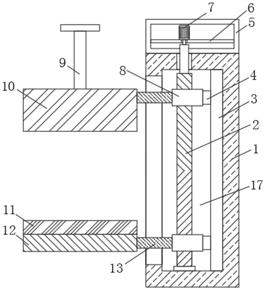
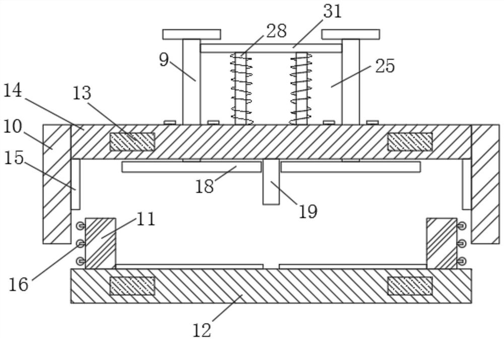
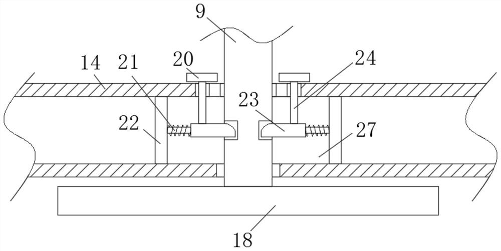
[0029] Example: such as Figure 1-6 As shown, a clamping device for financial bills of the present invention includes a housing 1, a fixed box 5 is fixedly connected to the top surface of the housing 1, and a first partition 6 is fixedly connected to the inside of the fixed box 5. The first partition The top of the plate 6 is provided with a first motor 7, the output end of the first motor 7 runs through the first partition 6, one side of the housing 1 is provided with a second clamping plate 14, and the two ends of the second clamping plate 14 are Both are fixedly connected with a fixed plate 10, the top of the second clamping plate 14 is symmetrically provided with two movable rods 9, a pulling mechanism 25 is arranged between the two movable rods 9, and two movable rods 9 are arranged inside the second clamping plate 14. Fixing mechanism 27, the first clamping plate 12 is provided below the second clamping plate 14, the top surface of the first clamping plate 12 is symmetri...


PUM


Abstract

A clamping device for financial bills according to the present invention comprises a casing, a fixed box is fixedly connected to the top surface of the casing, a first partition is fixedly connected inside the fixed box, and a first motor is arranged on the top of the first partition. , the output end of the first motor runs through the first partition, one side of the housing is provided with a second clamping plate, both ends of the second clamping plate are fixedly connected with fixing plates, and the top of the second clamping plate is symmetrical There are two movable rods, a pulling mechanism is arranged between the two movable rods, and two fixing mechanisms are arranged inside the second clamping plate. The beneficial effect achieved by the present invention is that bills of different thicknesses can be Adjust the clamping to avoid clamping only the specified number of bills. At the same time, the bills are clamped and fixed by the spring, so as to avoid the way of fixing and clamping the bills through the clamping parts, so that the excessively large The impact force is easy to cause damage to the bill.

Description

technical field [0001] The invention relates to a clamping device, in particular to a clamping device for financial bills, and belongs to the field of mechanical technology. Background technique [0002] In financial management, financial bills are an important bill certificate, which is not only related to individuals, but also to companies, so it is necessary to pay great attention to the storage of financial bills, but at present most financial bills are placed in the bill box, which makes It is inconvenient to use, and the bill box needs to be opened every time it is used, and then the picking operation is performed, thereby reducing the work efficiency, so a financial bill holding device is needed. [0003] Existing patent CN211335280U discloses a kind of bill clamping device for accounting which is convenient for sorting bills. The six clampers forming regular hexagons arranged on the bottom plate classify and clamp different kinds of bills. However, in the existing de...

Claims


Application Information

Patent Timeline
Patent Type & Authority Patents(China)
IPC IPC(8): B42F1/02
CPCB42F1/02
Inventor 杨洪祥
Owner 陈子越
Learn More