A combined multi-functional mold for common sprue rods

A gate rod, multi-functional technology, applied in manufacturing tools, casting molding equipment, metal processing equipment, etc., can solve the problems of high mold development cost, unadjustable mold cavity, poor positioning effect, etc., to achieve convenient transportation and carry, reduce Development cost, the effect of improving the guiding effect

Active Publication Date: 2021-11-23
UNITED LASHING PRECISION CASTING
View PDF0 Cites 0 Cited by
  • Summary
  • Abstract
  • Description
  • Claims
  • Application Information

AI Technical Summary

Problems solved by technology

[0004] The purpose of the present invention is to solve the disadvantages of simple structure, single function, inconvenient use, poor positioning effect and unadjustable mold cavity in the prior art, resulting in low work efficiency and high mold development cost, and proposes a combined Common gate rod multifunctional mold

Method used


Image

  • A combined multi-functional mold for common sprue rods
  • A combined multi-functional mold for common sprue rods
  • A combined multi-functional mold for common sprue rods

Examples


Embodiment 1

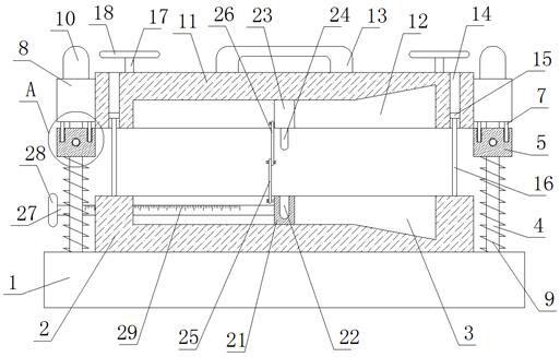
[0033] refer to Figure 1-5, a combination of commonly used sprue rod multifunctional molds, including a base 1, the top of the base 1 is fixedly connected with a lower mold body 2, the top of the lower mold body 2 is provided with a lower mold cavity 3, and the four corners of the top of the base 1 are uniform The vertical rods 4 are fixedly connected, and the four vertical rods 4 are respectively slidably provided with a slider 5 and connected with a connecting block 8, and the connecting block 8 is located above the slider 5 and is movably plugged with the slider 5. The same upper mold body 11 is fixedly connected between the four connection blocks 8, the bottom of the upper mold body 11 is provided with an upper mold cavity 12, the top of the upper mold body 11 is fixedly connected with a handle 13, and the top of the upper mold body 11 has four handles. The corners are all provided with through holes 14, and the four through holes 14 are slidingly connected with support r...

Embodiment 2

[0035] Further improved on the basis of embodiment one:

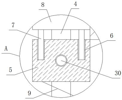
[0036] In the present invention, the tops of the four sliders 5 are symmetrically provided with two slots 6, and the insertion rods 7 are movably inserted in the eight slots 6, and the tops of the two insertion rods 7 on the same slider 5 Both extend to the top of the corresponding slider 5 and are respectively fixedly connected with the bottom of the corresponding connecting block 8, and the connecting block 8 is driven to move by pressing the upper mold body 11, and the sliding block 5 can be driven to slide at the same time.

[0037] In the present invention, one side of the four vertical rods 4 is sleeved with springs 9, and the two ends of the four springs 9 are fixedly connected to the top four corners of the lower mold body 2 and the bottom of the corresponding slider 5 respectively. The spring 9 can reset the slide block 5 .

[0038] In the present invention, the tops of one side of the four vertical rods 4 are...


PUM


Abstract

The invention belongs to the technical field of precision casting devices, in particular to a combined multi-functional mold with a commonly used sprue bar, aiming at the existing simple structure, single function, inconvenient use, poor positioning effect, and the mold cavity cannot be adjusted, resulting in low work efficiency , the problem of high mold development costs, the following scheme is now proposed, which includes a base, the top of the base is fixedly connected with a lower mold body, the top of the lower mold body is provided with a lower mold cavity, and the top four corners of the base are fixedly connected with Vertical rods, the four vertical rods are respectively provided with sliders for sliding sleeves and connecting blocks for penetrating sleeves. The present invention can play an effective role on the upper mold body through the cooperation of connecting blocks and vertical rods, through holes and supporting rods. The guiding effect, and through the cooperation of the rotating turntable and the round block, the upper mold body can be limited and clamped, and the overall movement of the first semi-circular slider and the second semi-circular slider can be used for the mold cavity. The length can be adjusted effectively, thus improving work efficiency.

Description

technical field [0001] The invention relates to the technical field of precision casting devices, in particular to a combined multi-functional mold for common sprue rods. Background technique [0002] The sprue rod is used for sand casting. It is made of wood or metal. In sand casting, this rod is used to form a gate channel, so that liquid metal can flow into the mold. If it is hand-molded, wood is better. , If it is a machine shape, it must be made of metal. [0003] The existing sprue rod mold has simple structure and single function, and cannot form an integrated operation, which leads to inconvenient use, poor positioning effect, and cannot effectively clamp the mold, and at the same time cannot fix the internal mold cavity. adjustment, resulting in only a single size gate bar, which not only reduces the work efficiency, but also increases the cost of mold development, so the present invention proposes a combined multifunctional gate bar mold to solve the problem of t...

Claims


Application Information

Patent Timeline
Patent Type & Authority Patents(China)
IPC IPC(8): B22C9/06B22C9/22
CPCB22C9/06B22C9/22
Inventor 赵维涛张晓杨飞萍
Owner UNITED LASHING PRECISION CASTING
Why Eureka
Try Eureka