Annular surrounding device

A ring and gear ring technology, which is applied in the field of ring wrapping devices, can solve the problems of increased winding cycle and production cost, and achieve the effects of improving efficiency, ensuring winding effect, and improving winding efficiency

Inactive Publication Date: 2016-07-20
BEIJING WDT MECHANICAL & ELECTRICAL TECH INST
View PDF7 Cites 4 Cited by
  • Summary
  • Abstract
  • Description
  • Claims
  • Application Information

AI Technical Summary

Problems solved by technology

[0005] The invention proposes a ring-shaped wrapping device, which solves the problems in the prior art that the winding cycle is increased and the production cost is increased due to manual winding of various insulating materials with different properties.

Method used


Image

  • Annular surrounding device
  • Annular surrounding device
  • Annular surrounding device

Examples


Embodiment Construction

[0034] The following will clearly and completely describe the technical solutions in the embodiments of the present invention with reference to the accompanying drawings in the embodiments of the present invention. Obviously, the described embodiments are only some, not all, embodiments of the present invention. Based on the embodiments of the present invention, all other embodiments obtained by persons of ordinary skill in the art without creative efforts fall within the protection scope of the present invention.

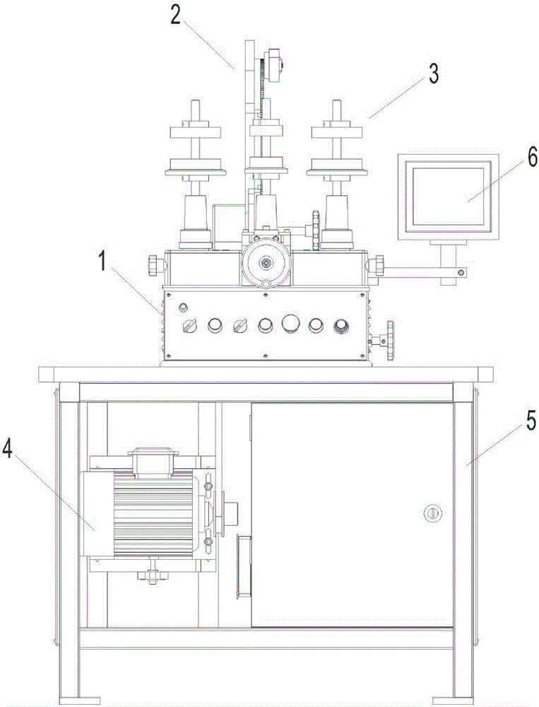
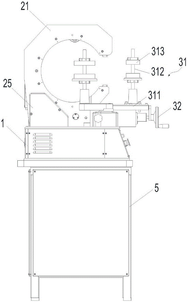
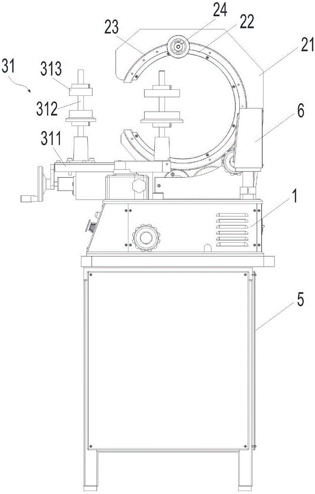
[0035] Such as Figure 1-3 Shown, a kind of annular wrapping device that the present invention proposes, comprises:

[0036] The rotary winding mechanism 2 is arranged on the base 1, and the corresponding operation is carried out through the support of the base 1. The clamping mechanism 3 is arranged on the base 1 and is adjacent to the rotary winding mechanism 2. The driving device 4 is connected with the rotary winding mechanism respectively. 2 is connected with...


PUM


Abstract

The invention provides an annular surrounding device. The problems that in the prior art, various insulation materials of different properties are wound in a manual manner, consequently, the winding period is prolonged, and the production cost is increased are solved. The annular surrounding device comprises a base arranged at the using place, a rotary winding mechanism used for driving the insulation materials to rotate and enabling the insulation materials to be wound on a coil and arranged on the base, a clamping mechanism used for fixing the coil and arranged on the base, and a driving device connected with the rotary winding mechanism and the clamping mechanism. According to the annular surrounding device, winding is ensured, the insulation materials can be evenly wound on the coil, in the winding process, manual intervention is not needed, and therefore the winding efficiency is improved while the winding effect is ensured; and that is, the cost is reduced while the efficiency is improved.

Description

technical field [0001] The invention relates to the field of wire winding, in particular to an annular winding device. Background technique [0002] During the use of the coil, in order to ensure its insulation, it is necessary to wrap insulating materials on its outer surface, so as to insulate the coil; [0003] Among them, some materials in the insulating material have a certain degree of elasticity, and the elastic insulating material needs to be tightened during winding, and then the tensioned insulating material is wound on the coil; [0004] The method in the prior art is to manually tighten the insulating material and wind the tightened material on the coil. However, this method cannot ensure that the tension of the insulating material is constant, resulting in the winding on the coil. The force received by the insulating material is not uniform, resulting in different thicknesses of the insulating material after winding, and different forces, which affect the servi...

Claims


Application Information

Patent Timeline
Patent Type & Authority Applications(China)
IPC IPC(8): B65B11/02B65B25/24
CPCB65B11/025B65B25/24
Inventor 光和田
Owner BEIJING WDT MECHANICAL & ELECTRICAL TECH INST
Why Eureka
Try Eureka