Piston unit and hydrostatic radial piston machine

A radial piston engine, hydrostatic technology, applied in the direction of reciprocating piston engine, piston, barrel piston, etc., can solve problems such as trouble and reduce degree, and achieve the effect of improving durability, reducing friction and improving starting efficiency.

Active Publication Date: 2021-12-07
ROBERT BOSCH GMBH
View PDF8 Cites 0 Cited by
  • Summary
  • Abstract
  • Description
  • Claims
  • Application Information

AI Technical Summary

Problems solved by technology

Although relatively good frictional properties can thus be obtained between the contained rollers and the roller housing, there is still a desire for a degree of friction reduction beyond this
Furthermore, it is relatively cumbersome to process and (pre)assemble composite bearing materials into bearing shells

Method used


Image

  • Piston unit and hydrostatic radial piston machine
  • Piston unit and hydrostatic radial piston machine
  • Piston unit and hydrostatic radial piston machine

Examples


Embodiment Construction

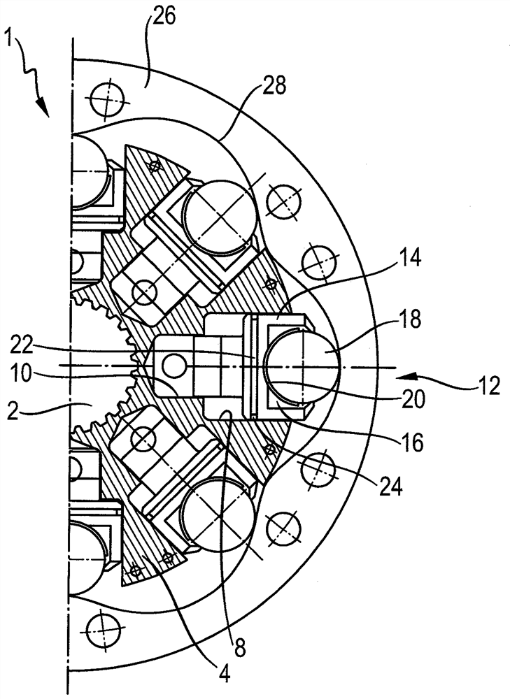
[0042]figure 1 An exemplary embodiment of the hydrostatic radial piston machine 1 according to the invention is shown in a section perpendicular to the axis of rotation of the hydrostatic radial piston machine 1 . In this exemplary embodiment, the hydrostatic radial piston machine 1 is a radial piston motor with an external piston support. The basic function of such a hydrostatic radial piston machine is described, for example, in DE 40 37 455 C1.

[0043] The hydrostatic radial piston machine 1 has a centrally arranged shaft 2 , by means of which an element fastened thereto (not shown here) can be driven. The shaft 2 is driven by a surrounding rotor 4 in which a plurality of cylinders 6 are formed. In the exemplary embodiment, the hydrostatic radial piston machine 1 has exactly eight cylinders 6, of which figure 1 Only three cylinders are shown in full and two further cylinder halves are also shown in each case. The cylinders 6 are arranged radially or star-shaped around t...


PUM


Abstract

The invention relates to a piston unit and to a hydrostatic radial piston machine provided with at least one such piston unit. The piston unit has a piston with a rolling body receptacle for rotatably mounting the rolling bodies. According to the invention, the rolling element receptacle has a bearing surface which has a surface coating of a polymer compound or a ceramic surface coating.

Description

technical field [0001] The invention relates to a piston unit and a hydrostatic radial piston machine with such a piston unit, wherein the piston unit has a piston with a function for rotatably actuating the rolling bodies. Mounted rolling body housing. Background technique [0002] A hydrostatic radial piston machine of this type is known, for example, from DE 40 37 455 C1. Such a radial piston machine has a rotor configured as a cylinder, in which a plurality of piston units is guided displaceably in the radial direction. Each of the piston units has a piston which is guided in the cylinder bore of the cylinder and whose end region protrudes from the cylinder in radial direction. The segments are supported by rolling bodies on stroke disks or disk cams which are held in a fixed position in the housing of the hydrostatic radial piston machine, so that the piston moves according to the stroke curve of the stroke disk. Realize the stroke. A disadvantage of such a piston u...

Claims


Application Information

Patent Timeline
Patent Type & Authority Patents(China)
IPC IPC(8): F03C1/28F03C1/247F16J1/02F01B13/06F04B53/14F04B1/10F04B39/00F04B27/06
CPCF01B13/06F03C1/0406F03C1/247F04B1/10F04B27/06F04B39/0005F04B53/14F16J1/001F16J1/01F16J1/02F01B1/0603F01B1/0644F01B1/0651F01B1/0655F01B9/06F04B1/0408F04B1/0474F04B1/107
Inventor G.克莫德K.基尔罗伊A.麦克菲
Owner ROBERT BOSCH GMBH
Why Eureka
Try Eureka