
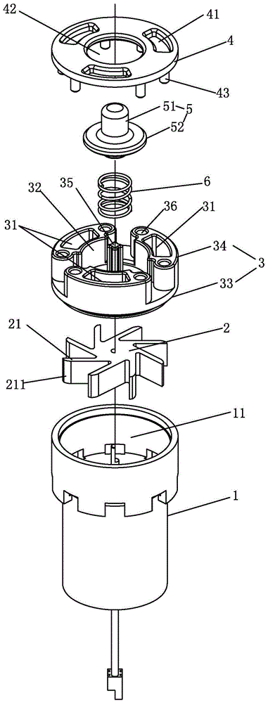
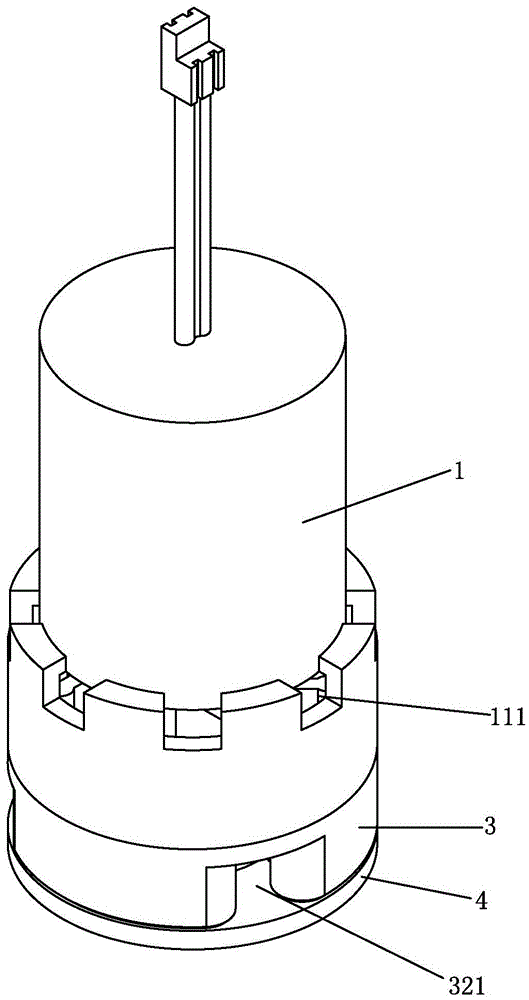
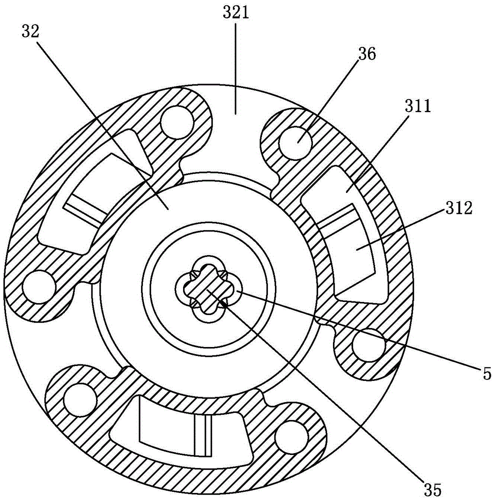
Hydroelectric generator with flow control function, and shower faucet

A hydroelectric generator and flow control technology, which is applied in hydroelectric power generation, engine components, machines/engines, etc., can solve problems such as the inability of the engine to generate electricity, the insufficient speed of the impeller and the impeller, and the inability to push the water flow, so as to facilitate production, assembly, and cost. Low, simple structure effect

Active Publication Date: 2016-07-20
JOMOO KITCHEN & BATHROOM
View PDF11 Cites 8 Cited by
  • Summary
  • Abstract
  • Description
  • Claims
  • Application Information

AI Technical Summary

Problems solved by technology

However, in the actual application process, the following problems have arisen: under low water pressure, the water flow cannot drive the impeller to rotate or the impeller speed is insufficient, resulting in the engine being unable to generate electricity or insufficient power generation; under high water pressure, although the hydroelectric generator can operate normally Power generation, but also play a certain role in current limiting, resulting in insufficient back-end flow
In this regard, a hydraulic generator has appeared in the prior art, which solves the above-mentioned problems by designing a bypass chamber and performing flow diversion or confluence. This can certainly solve the above-mentioned problems, but it also has complex structures, large volumes, and high costs. Inadequacies

Method used


Image

  • Hydroelectric generator with flow control function, and shower faucet
  • Hydroelectric generator with flow control function, and shower faucet
  • Hydroelectric generator with flow control function, and shower faucet

Examples


Embodiment 2

[0044] A kind of hydraulic generator 1 with flow control of the present invention differs from Embodiment 1 in that: the water injection hole 312 is an oblique hole, such as Figure 9 As shown, the arrow in the figure indicates the jetting direction of the water flow.

[0045] Under the premise that the slope of the inclined hole in the second embodiment is consistent with the slopes of the first diversion slope 3121 and the second diversion slope 3122 in the first embodiment, because in the first embodiment, the inner wall of the water injection hole 312 is provided with the The first diversion slope 3121 and the second diversion slope 3122, and a horizontal hole section 3123 makes a transition between the two, so that the angle at which the water sprays from the water jet hole 312 described in Embodiment 1 is smaller than that of the water from the embodiment 1. The angle at which the water jet hole 312 is sprayed out in the second example.

[0046] After the water is eject...


PUM


Abstract

The invention discloses a hydroelectric generator with a flow control function, and a shower faucet. The hydroelectric generator comprises an electric generator body and a valve. The valve is provided with a first runner and a second runner which are capable of being communicated with a same water supply pipeline. The first runner is communicated with an impeller cavity of the electric generator body. Through the first runner, water flow is pressurized and conveyed into the impeller cavity of the electric generator body so as to drive an impeller to rotate. The impeller cavity is provided with a water outlet. The valve is provided with a control valve body which is controlled by water supply pressure and can be reset. The control valve body controls the second runner to discharge water or not. According to the hydroelectric generator and the shower faucet, under the low water pressure condition, water can be made to flow the impeller cavity of the electric generator body completely, and power generation of the electric generator body is not influenced; and under the high water pressure condition, part of water flows out through the second runner and provides efficient flow for the rear end together with water flowing out from the impeller cavity, so that normal flowing of the water flow is not hindered. The hydroelectric generator and the shower faucet further have the characteristics of being simple in structure, convenient to produce and assemble, low in cost and the like.

Description

technical field [0001] The invention relates to a hydraulic generator, in particular to a hydraulic generator with flow control and a shower faucet. Background technique [0002] The hydroelectric generator uses the impulsive force of water to push the impeller of the generator to rotate, and the rotor of the generator performs the movement of switching the magnetic force line with the rotation of the impeller, thereby generating an induced electric potential. At present, hydroelectric generators are more and more widely used in the field of sanitary ware. They mostly use water outlet devices, such as shower faucets and showers, as carriers, and generate electricity without affecting the water outlet of the water outlet terminal. However, in the actual application process, the following problems have arisen: under low water pressure, the water flow cannot drive the impeller to rotate or the impeller speed is insufficient, resulting in the engine being unable to generate elec...

Claims


Application Information

Patent Timeline
Patent Type & Authority Applications(China)
IPC IPC(8): F16K51/00F16K27/00F16K37/00F03B13/00F03B3/12
CPCF03B3/121F03B3/125F03B13/00F16K27/00F16K37/0025F16K51/00Y02E10/20
Inventor 林孝发林孝山梁绍团董军利
Owner JOMOO KITCHEN & BATHROOM
Learn More