Fuel accessory component oil leakage volume testing apparatus

A technology for a test device and fuel accessories, which is applied in the field of test devices for repairing oil leakage of fuel accessories, can solve the problems of unstable oil leakage, low troubleshooting rate, lack of oil leakage, etc. The effect of accurate oil leakage and strong reliability

Inactive Publication Date: 2016-07-20
XIAN AERO ENGINE CONTROLS
View PDF7 Cites 3 Cited by
  • Summary
  • Abstract
  • Description
  • Claims
  • Application Information

AI Technical Summary

Problems solved by technology

[0003] This device is a general-purpose flushing device for the valve assembly, which is used to replace the current oil leakage test device for this component. There are deficiencies in the test control process, mainly in the following two aspects, see figure 2 : 1) There are many sealing positions and sealing methods of the device. During long-term use, due to the wear of the rubber ring or improper clamping, it is easy to cause the loss of oil leakage and affect the accuracy of the test; 2) The structure of the device is open The structure, the oil leakage part of the part is completely exposed to the outside, when collecting the oil leakage, the oil leakage is collected through the measuring cup, which is easily disturbed by external conditions
[0004] Due to the use of general test equipment to test the components, the amount of oil leakage is unstable and the accuracy is also controversial during the assembly and debugging process of the complete accessories. Performance debugging requirements, in order to reduce the number of troubleshooting and improve the pass rate of assembly and debugging, it is urgent to invent a special test device for the oil leakage test of the valve assembly, to achieve the purpose of accurate and reliable test data, low troubleshooting rate and easy operation

Method used


Image

  • Fuel accessory component oil leakage volume testing apparatus
  • Fuel accessory component oil leakage volume testing apparatus
  • Fuel accessory component oil leakage volume testing apparatus

Examples


Embodiment Construction

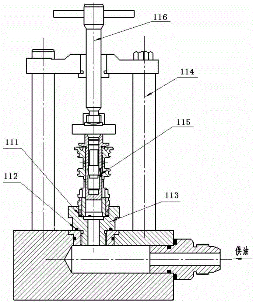
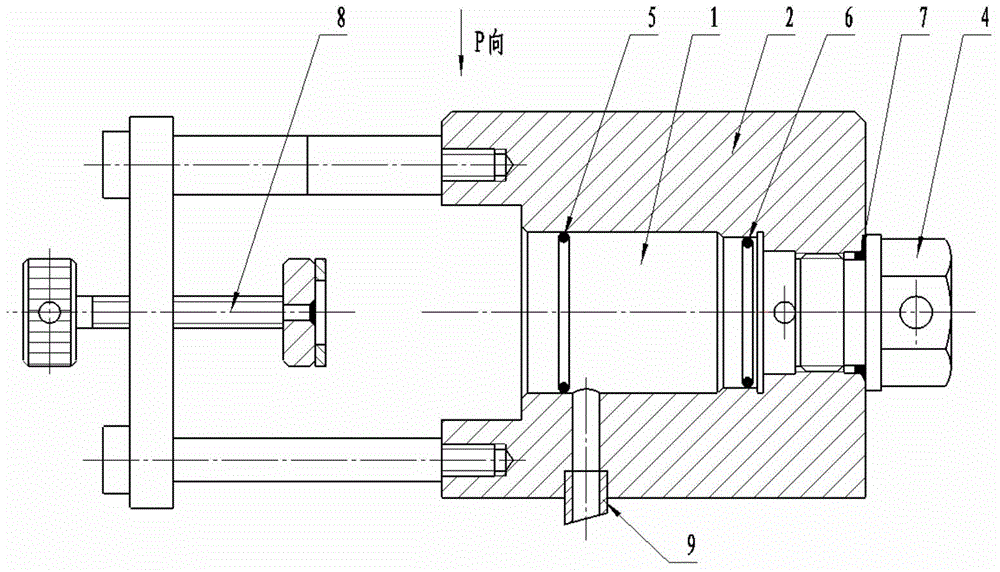
[0020] see Figure 3.1 — Figure 3.3 , the present invention according to the design technical requirements of the oil leakage test of the valve pair, track and analyze the existing test control method and process, according to the technical defects and deficiencies in the test control process, finally invented the following special oil leakage For the test device, see Figure 3.1 — Figure 3.3 Shown:

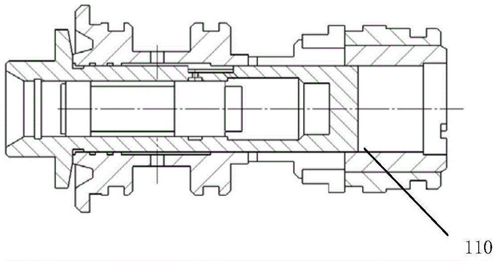
[0021] The test device includes a closed chamber 1, a closed chamber base 2 connected with the closed chamber 1, an oil inlet 3 arranged on the wall of the closed chamber and a screw plug 4 installed on the base; Rings 5 ​​and 6; the end face of screw plug 4 is equipped with rubber ring 7; the test part, rubber ring 5, rubber ring 6, rubber ring 7, closed cavity base 2 and screw plug 4 completely seal the oil leakage site. An oil connection port 9 is arranged on the base 2 of the closed cavity, and the position of the oil connection port 9 is located between the rubber ring...


PUM


Abstract

The invention discloses a fuel accessory component oil leakage volume testing apparatus which is configured in such that: the testing apparatus is provided with an enclosed cavity which is connected to a enclosed cavity pedestal, an oil inlet opening which is arranged on the wall of the enclosed cavity, and a plug which is disposed on the pedestal; two rubber rings are axially arranged along the inner wall inside the enclosed cavity; the two rubber ring, the enclosed cavity pedestal and the plug completely enclose oil leakage parts. According to the invention, the testing apparatus is characterized in such that: the rubber rings adopt radial sealing in order to provide reliable sealing for a test; side opening for oil leakage: specific oil receiving parts are designed to provide oil leakage volume information in an accurate manner, which makes oil leakage volume more accurate and reliable; an integrated clamp has a simple structure; the apparatus avoids influence from ambient environment and makes oil leakage volume accurate and reliable; a detachable apparatus is also provided with a specific to bar for detaching the component, which is easy and reliable.

Description

technical field [0001] The invention belongs to the field of engine testing, and in particular relates to an oil leakage test device for repairing fuel accessories. Background technique [0002] The current valve couple, see figure 1 , the general device used in oil leakage test see figure 2 , the specific test method is carried out according to the following steps: (1) combined test device: put the rubber rings 111, 112 into the transition sleeve 113, then put the transition sleeve 113 into the clamp 114, and the assembly of the test device is about to be completed; (2) clamping test Parts: put the valve assembly 115 into the combined test fixture, and press the assembly through the handle 116; (3) Oil leakage test: inject a certain pressure of fuel from the oil supply, and check the oil leakage window 110 through the measuring cup (see figure 1 ) The size of the oil leakage in the gap. [0003] This device is a general-purpose flushing device for the valve assembly, wh...

Claims


Application Information

Patent Timeline
Patent Type & Authority Applications(China)
IPC IPC(8): G01M3/04
CPCG01M3/04G01M3/025
Inventor 李浩杜龙龙林艺张忠荣刘群勃魏立
Owner XIAN AERO ENGINE CONTROLS
Why Eureka
Try Eureka