
Plasma etching device for slicing wafer and method for loading and unloading wafer

An etching device and plasma technology, applied in the directions of transportation and packaging, conveyor objects, discharge tubes, etc., can solve the problems of disordered arrangement of chips and damage to films, etc.

Active Publication Date: 2016-07-20
ADVANCED MICRO FAB EQUIP INC CHINA
View PDF6 Cites 5 Cited by
  • Summary
  • Abstract
  • Description
  • Claims
  • Application Information

AI Technical Summary

Problems solved by technology

The existence of this film can partially alleviate the above problems, but there are still major defects: 1), the columnar thimble may damage the film; (2), due to the existence of the film, the thimble can lift the film and all chips adhered to the film, However, the chip arrangement will be disordered during the jacking process

Method used


Image

  • Plasma etching device for slicing wafer and method for loading and unloading wafer
  • Plasma etching device for slicing wafer and method for loading and unloading wafer
  • Plasma etching device for slicing wafer and method for loading and unloading wafer

Examples


Embodiment Construction

[0050] The plasma etching apparatus for wafer slicing and the method for loading and unloading wafers will be described below in conjunction with the accompanying drawings. It should be emphasized that this is only an exemplary description, and other implementations of the present invention are not excluded.

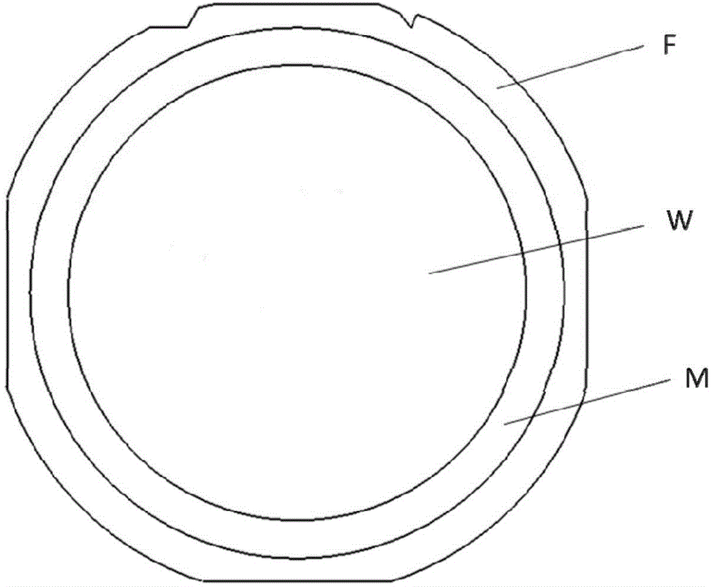
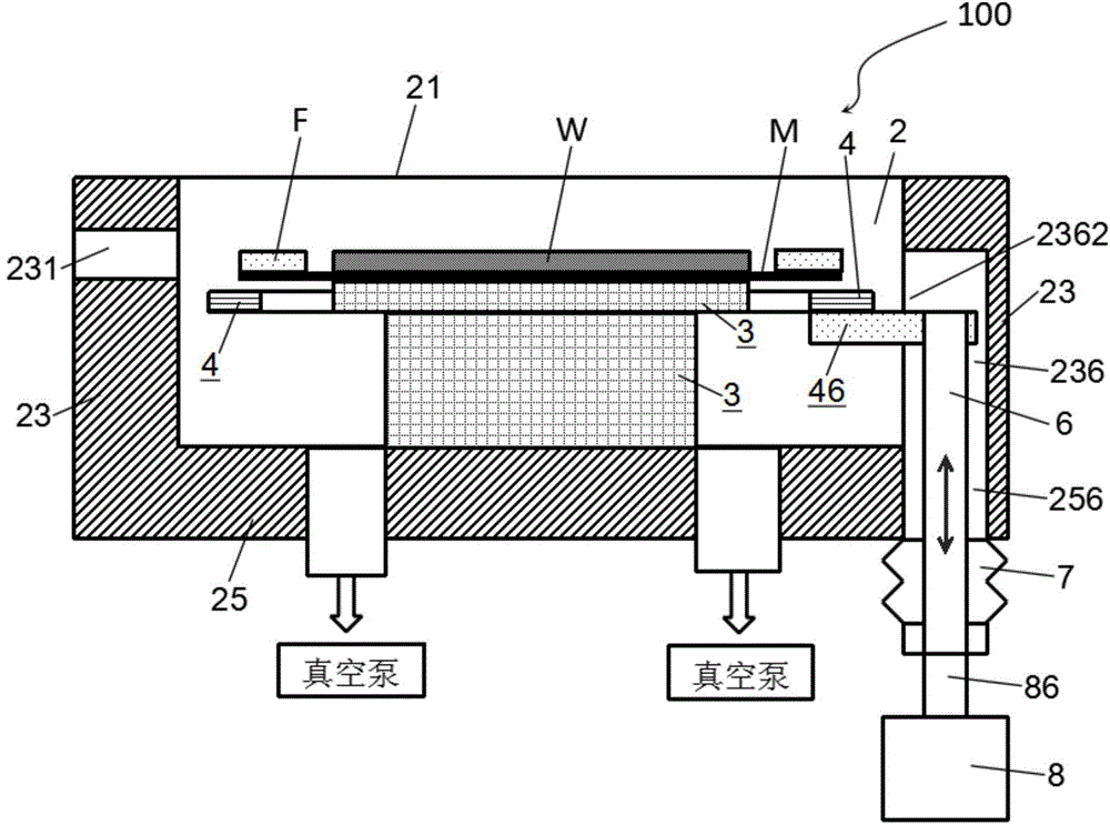
[0051] image 3 It is a schematic structural diagram of a plasma etching apparatus for wafer dicing (waferdicing) according to an embodiment of the present invention. In this device, the adhesive material between adjacent chips (or dies, DIEs) on the wafer is removed by plasma etching to form a dividing groove, so that the chips are independent of each other. In order to prevent damage to the structure of the chip itself in the process of slicing the chip, a mask layer, such as photoresist, can be coated on the surface of the chip area, and the mask layer does not cover the adhesion material between the chips. As a special slicing method, in the slicing process, the plasma...


PUM


Abstract

The invention provides a plasma etching device for slicing a wafer and a method for loading and unloading the wafer. A to-be-sliced wafer enters the etching device along with a thin film- frame structure; the thin film-frame structure comprises an annular frame and a thin film; the thin film is arranged on the frame and covers an opening in the center of the frame; the wafer is arranged on the upper surface of the thin film in the opening; the etching device comprises a reaction chamber, a base, a lifting ring, a lifting rod and a drive component; the reaction chamber is surrounded by a top wall, a side wall and a bottom wall; the base is arranged in the reaction chamber and is used for supporting the wafer; the lifting ring is arranged on the periphery of the base and can lift; the lifting ring is in contact with the frame on the periphery of the wafer and lifts or sinks the frame in the lifting process; the lifting rod is used for driving the lifting ring to carry out lifting motion; one end of the lifting rod is used for being connected with the lifting ring and the other end passes through a hole in the bottom wall of the reaction chamber to extend out of the reaction chamber; and the drive component is located outside the reaction chamber and is used for driving the lifting rod.

Description

Technical field [0001] The present invention relates to an apparatus for wafer dicing (waferdicing) using an etching method, and more particularly to a component and method for loading and unloading wafers in the above-mentioned apparatus. Background technique [0002] In the field of semiconductor device manufacturing, a series of the same devices are usually fabricated in different areas on the same wafer surface, and then the wafer is cut into individual functional device units (ie, chips, DIEs). The above-mentioned dicing process is generally called wafer dicing (waferdicing). Traditional wafer slicing is usually done with the help of cutting tools. [0003] In recent years, there have been some research and exploration on the use of etching methods to realize wafer slicing, such as the patent application WO2014 / 062582A1 published on April 24, 2014. These research theories noticed some possible problems and proposed solutions. [0004] However, these existing research theories...

Claims


Application Information

Patent Timeline
IPC IPC(8): H01J37/32H01L21/677
Inventor 黄允文陈妙娟何乃明
Owner ADVANCED MICRO FAB EQUIP INC CHINA
Learn More