Thermal management device and power source device
A technology of thermal management and heat conduction sheet, applied in circuits, electrical components, secondary batteries, etc., can solve the problems of shortened battery life, poor battery performance, and inability to discharge heat in time, to reduce thermal resistance and improve thermal conductivity. Effect
- Summary
- Abstract
- Description
- Claims
- Application Information
AI Technical Summary
Problems solved by technology
Method used
Image

Examples
no. 1 example
[0040] For a first example, see Figure 1 to Figure 4
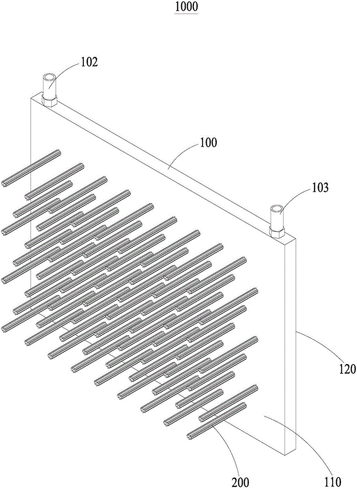
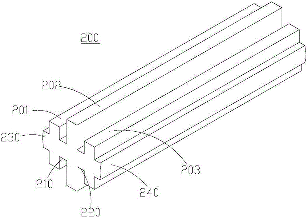
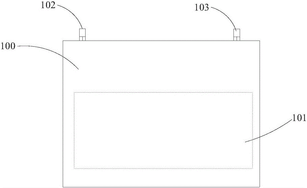
[0041] Such as figure 1 As shown, the thermal management device 1000 provided in this embodiment includes a liquid cold plate 100 and at least one heat conduction fin 200 . Wherein, the liquid cold plate 100 includes a first side 110 and a second side 120 oppositely disposed. The inside of the liquid cooling plate 100 is provided with a liquid storage tank 101, and a liquid inlet 102 and a liquid outlet 103 communicated with the liquid storage tank 101. For details, please refer to figure 2 The plan view of the liquid cold plate 100 is shown. The liquid inlet 102 , the liquid outlet 103 and the liquid storage tank 101 cooperate together to form a liquid circulation channel. see again image 3 , image 3 is a three-dimensional structure diagram of the heat conduction fin 200 . The heat conduction fins 200 include a first heat conduction sheet 201 , a second heat conduction sheet 202 and a third heat conduction shee...
no. 2 example
[0050] For a second example, see Figure 5 to Figure 8
[0051] The thermal management device 1000 and the power supply device 2000 provided by the second embodiment of the present invention have the same realization principles and technical effects as those of the first embodiment. For a brief description, for the parts not mentioned in the second embodiment, please refer to the first Corresponding content in an embodiment.
[0052] Figure 5 It is a three-dimensional structural diagram of the power supply device 2000 provided by the second embodiment. Compared with the first embodiment, in the power supply device 2000 provided by the second embodiment, the thermal management device 1000 further includes a thermally conductive insulating pad 400 . The heat conducting and insulating pad 400 is attached to the first side 110 of the liquid cooling plate 100 .
[0053] Furthermore, in this embodiment, the battery module 300 includes not only the plurality of single batteries ...
no. 3 example
[0062] Figure 9 It is another power supply device 2000 provided by the third embodiment of the present invention. In the power supply device 2000 , the liquid cooling plate 100 included in the thermal management device 1000 may be respectively connected with heat conduction fins 200 on the opposite first side 110 and the second side 120 . When two battery modules 300, respectively defined as the first battery module and the second battery module, are connected in series, the liquid cooling plate 100 connected to the heat conduction fins 200 on both sides is arranged on the total of the first battery module. The connection between the positive terminal and the total negative terminal of the second battery module. Wherein, the heat conduction fins 200 on the first side 110 extend into the first battery module through the first collector plate 3031 and the first support plate 3021 of the first battery module, and are placed in the first battery module. gaps between adjacent si...
PUM
 Abstract
Description
Claims
Application Information
 - R&D
- Intellectual Property
- Life Sciences
- Materials
- Tech Scout
- Unparalleled Data Quality
- Higher Quality Content
- 60% Fewer Hallucinations
Browse by: Latest US Patents, China's latest patents, Technical Efficacy Thesaurus, Application Domain, Technology Topic, Popular Technical Reports.
© 2025 PatSnap. All rights reserved.Legal|Privacy policy|Modern Slavery Act Transparency Statement|Sitemap|About US| Contact US: help@patsnap.com