Permanent magnet motor employing PCB winding

A permanent magnet motor and winding technology, which is applied in the shape/style/structure of winding conductors, electrical components, and electromechanical devices, etc., can solve the problems of difficult winding of motor windings, complicated processes, etc., to suppress eddy current loss, improve efficiency, The effect of energy saving

Inactive Publication Date: 2016-07-20
SHENZHEN ACAD OF AEROSPACE TECH
View PDF8 Cites 2 Cited by
  • Summary
  • Abstract
  • Description
  • Claims
  • Application Information

AI Technical Summary

Problems solved by technology

However, for several types of motors such as coreless permanent magnet synchronous motors, ironless permanent magnet linear motors and slotless permanent disk motors, the winding of motor windings is more difficult and the process is complicated.

Method used


Image

  • Permanent magnet motor employing PCB winding
  • Permanent magnet motor employing PCB winding
  • Permanent magnet motor employing PCB winding

Examples


Embodiment Construction

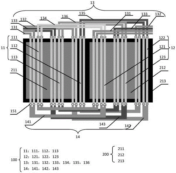
[0017] An example of the present invention is figure 1 As shown, only the partial structures of the PCB assembly 100 and the magnetic steel assembly 200 are shown. figure 1 middle:

[0018] 111 is the motor PCB winding U-phase winding conductor U1,

[0019] 112 is the motor PCB winding V-phase winding conductor V1,

[0020] 113 is the motor PCB winding W phase winding conductor W1,

[0021] 121 is the motor PCB winding U-phase winding conductor U2,

[0022] 122 is the motor PCB winding V-phase winding conductor V2,

[0023] 123 is the motor PCB winding W phase winding conductor W2,

[0024] 131 is the U-phase end A1 of the motor PCB winding,

[0025] 132 is the motor PCB winding V-phase end A1,

[0026] 133 is the motor PCB winding W-phase end A1,

[0027] 134 is the motor PCB winding U-phase end A2,

[0028] 135 is motor PCB winding V-phase end A2,

[0029] 136 is the motor PCB winding W-phase end A2,

[0030] 141 is the U-phase end B of the motor PCB winding,

[...


PUM


Abstract

The invention discloses a permanent magnet motor employing a PCB winding. A PCB structure is adopted by the winding of the motor; in order to reduce eddy-current loss under the condition of a relatively high current of the winding of the motor, on one hand, a single wide winding conductor in a main magnetic field is converted into a plurality of narrow winding conductors in parallel; and on the other hand, a single wide end part conductor at one end part is at least converted into a plurality of narrow end part conductors in parallel; parallel branches of two parts are the same in number; and the parallel branches of the two parts are connected one by one in series. According to the permanent magnet motor employing the PCB winding, the eddy current loss of the PCB winding is greatly suppressed; additional moment generated by an eddy current is reduced; the motor output is improved; and the permanent magnet motor has important significance in energy conservation and improvement of the efficiency of the motor. A rigid PCB and a flexible PCB can be adopted by the PCB winding disclosed by the invention; and the permanent magnet motor can be applied to an axial-flux motor, a radial-flux motor, a rotary motor or a linear motor and the like.

Description

technical field [0001] The invention relates to the field of motors, in particular to a permanent magnet motor using PCB windings. Background technique [0002] In the existing common permanent magnet motor, the windings are mostly placed in the iron core slot and wound along the teeth of the motor iron core. However, for several types of motors such as coreless permanent magnet synchronous motors, ironless permanent magnet linear motors and slotless permanent disk motors, the winding of motor windings is more difficult and the process is complicated. Contents of the invention [0003] The technical problem to be solved by the present invention is to provide a simple permanent magnet motor using PCB windings for the defects of motor winding processes such as coreless permanent magnet synchronous motors, coreless permanent magnet linear motors and slotless permanent disk motors. motor. [0004] In order to solve the above technical problems, the present invention provides...

Claims


Application Information

Patent Timeline
Patent Type & Authority Applications(China)
IPC IPC(8): H02K3/26
CPCH02K3/26H02K2213/03
Inventor 王孝伟
Owner SHENZHEN ACAD OF AEROSPACE TECH
Why Eureka
Try Eureka