Motor drive circuit and method with frequency setting and correcting functions

Active Publication Date: 2005-08-23
PROLIFIC TECH INC
View PDF9 Cites 6 Cited by
  • Summary
  • Abstract
  • Description
  • Claims
  • Application Information

AI Technical Summary

Benefits of technology

[0023]In summary, the invention discloses a motor drive circuit and method with frequency setting and correcting functions, wherein a rotation frequency setting signal is generated to set and correct the real rotation frequency of the motor. Thus, it is possible to compensate for the structure errors that occur during the manufacturing processes and to compensate for erro

Problems solved by technology

This is because when heat is concentrated inside the products and cannot be effectively dissipated, individual electrical elements, or even the entire electrical system may experience a failure.
That is, the controller can only output a non-corrected control signal in a one-way manner.
Driver can not control the motor speed with the conventional driving method.
Next, when the conventional brushless DC motor is operating, although the motor rotation speed is constant within the primal time period, the motor may lose its optimum standard rotation frequency after a period of time has elapsed.
In this case, the motor rotation speed may wander, resulting in undesired phenomena (e.g., unstable gas quantity, loud motor noise, and vibration), and the system operation may be negatively influenced.
The conventional brushless DC motor may have inherent structural defects from the manufacturing processes, such as mechanical assembly err

Method used


Image

  • Motor drive circuit and method with frequency setting and correcting functions
  • Motor drive circuit and method with frequency setting and correcting functions
  • Motor drive circuit and method with frequency setting and correcting functions

Examples


Example

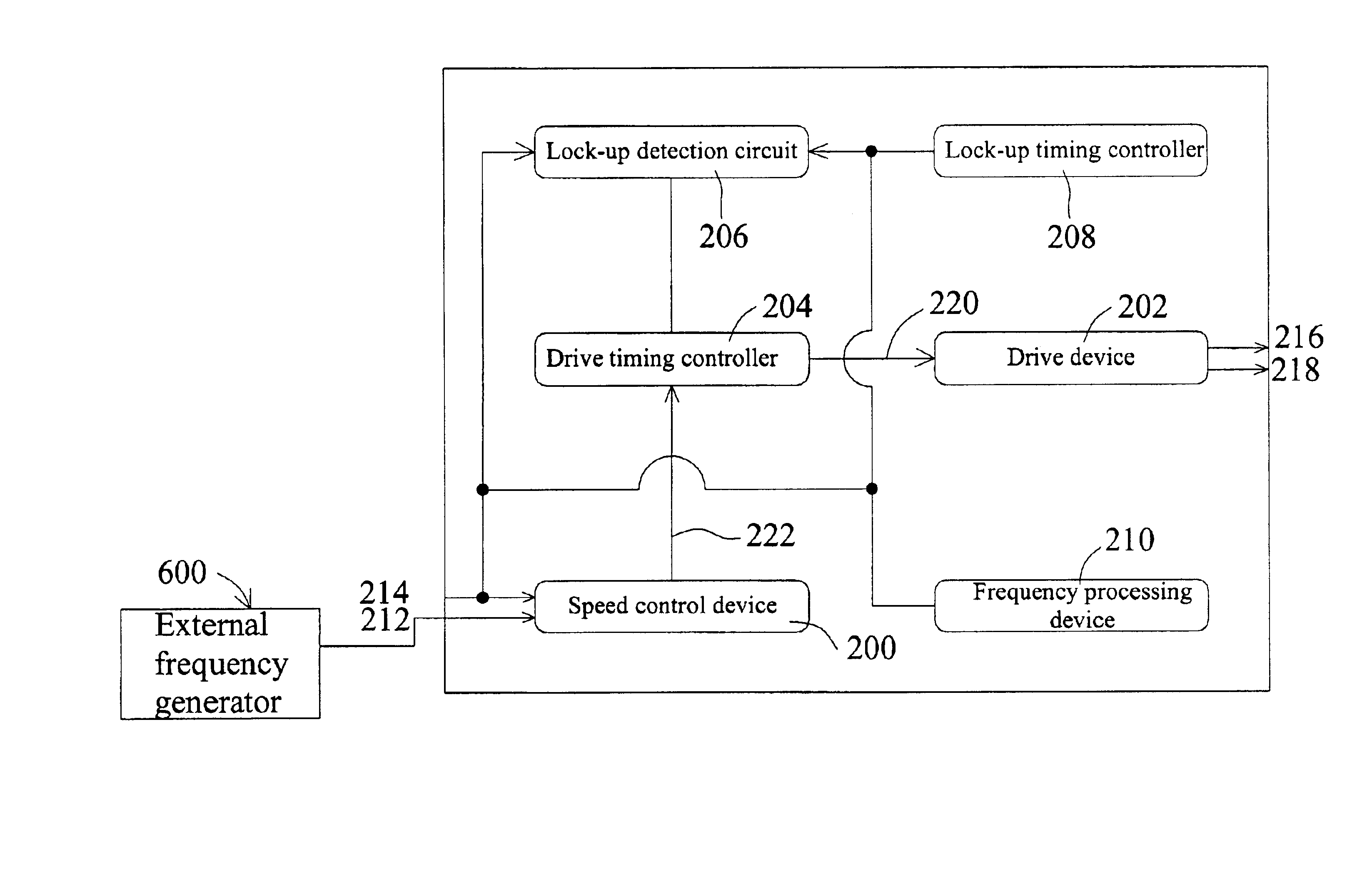
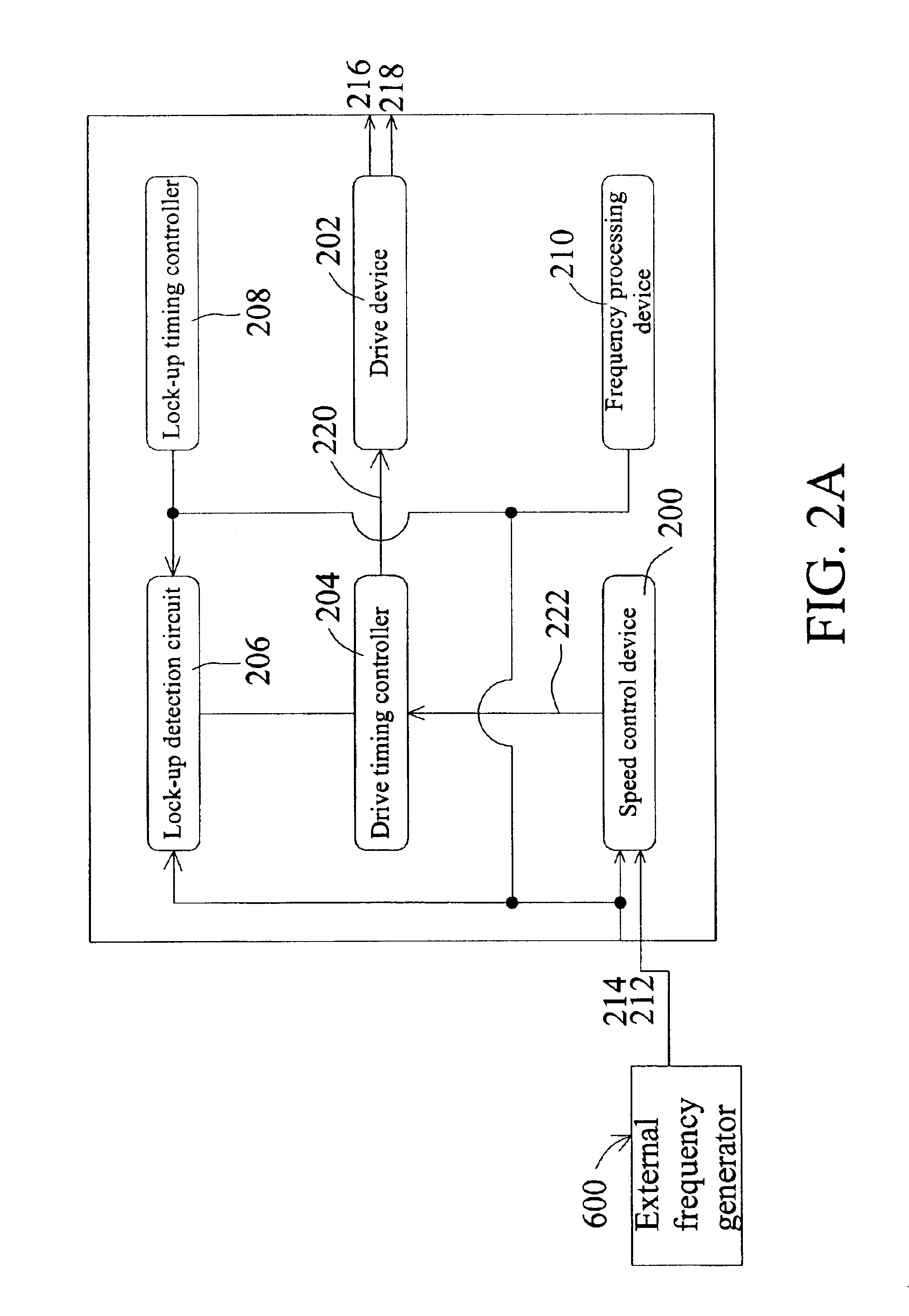
[0044]FIGS. 4A to 4C show a drive circuit according to a first embodiment of the invention. The drive device 202 of FIG. 2A has a first power output terminal 216, a second power output terminal 218, and a signal input terminal 220. The first power output terminal 216 and the second power output terminal 218 are coupled to the motor coil, and the signal input terminal 220 is coupled to the drive timing controller 204. The drive device 202 has multiple transistors to generate a power drive signal, and utilizes the sensor to sense the corrected rotation speed, which immediately feeds the correction sense signal back to the speed control device 200. Therefore, a closed loop control is constructed to automatically correct the rotation frequency of the motor.

[0045]In an embodiment of the invention, as shown in FIG. 4A, a single coil 408, which has first and second terminals, is shown. The drive device 202 includes a first transistor 400, a second transistor 402, a third transistor 404, an...

Example

[0049]FIG. 4D shows a drive device according to a second embodiment of the invention. The motor has a first coil 420 and a second coil 422, each of which has a first terminal connected to the power supply end VCC. And the second terminals of the first coil 420 and the second coil 422 are coupled to the first power output terminal 216 and the second power output terminal 218. The drive device 202 includes a first transistor 424 and a second transistor 426, each of which has a source, a gate, and a drain. In the first transistor 424, its source is connected to the ground end GND, its drain is the second power output terminal 218 and is connect to the second terminal of the first coil 420, and its gate is connected to the drive timing controller 204. In the second transistor 426, its source is connected to the ground end GND, its drain is the second power output terminal 218 and is coupled to the second terminal of the second coil 422, and its gate is connected to the drive timing cont...


PUM


Abstract

A motor drive circuit and method with frequency setting and correcting functions. The drive circuit includes a speed control device, which simultaneously receives a sense signal and a rotation frequency signal. A pulse width modulation signal capable of modulating a duty ratio may be generated by a pulse width modulation method. The pulse width modulation signal is then transferred to a drive timing controller that generates a timing control signal to control output timing of a power drive signal for the drive circuit. Meanwhile, a sensor is used to detect a motor and to generate a correction sense signal, which is immediately fed back to the speed control device to form a closed loop control, so that the rotation frequency of the motor may be automatically corrected and set.

Description

[0001]This application claims the benefit of Taiwan application Ser. No. 091104641, filed Mar. 12, 2002.BACKGROUND OF THE INVENTION[0002]1. Field of the Invention[0003]The invention relates to a motor drive circuit, and more particularly to a motor drive circuit and method with frequency setting and correcting functions.[0004]2. Description of the Related Art[0005]Products such as notebook computers, scanners, power supplies, and precise electronic instruments are widely used as part of a highly developed information technology industry. In general, it is very important when working with electrical products to quickly dissipate heat in order to obtain maximum efficiency. This is because when heat is concentrated inside the products and cannot be effectively dissipated, individual electrical elements, or even the entire electrical system may experience a failure. A brushless DC motor fan is usually used as a device for dissipating heat so that the electrical elements within the syste...

Claims


Application Information

Patent Timeline
IPC IPC(8): H02P6/08
CPCH02P6/08
Inventor HSU, CHIA-CHANGCHEN, YEN-JOHN
Owner PROLIFIC TECH INC
Why Eureka
Try Eureka