Hook-type electromagnetic field device of full-diameter single crystal furnace

An electromagnetic field, single crystal furnace technology, applied in the direction of single crystal growth, post-processing device, crystal growth, etc., can solve the problems of troublesome assembly of the upper and lower coils, large overall mass of the integral shield, difficult to assemble and maintain, etc. Material saving, continuously adjustable magnetic field strength, simple installation and commissioning

Active Publication Date: 2011-08-17
杭州慧翔电液技术开发有限公司 +1
View PDF5 Cites 7 Cited by
  • Summary
  • Abstract
  • Description
  • Claims
  • Application Information

AI Technical Summary

Problems solved by technology

The disadvantage of this method is that the hollow copper tube must meet a minimum size, so under the limitation of the actual installation size, the number of coil turns in the hollow solenoid method will be limited, because the magnetic field strength is related to the number of coil turns and the current through the coil is proportional to the product, and in order to ensure that the magnetic field strength is large enough, it is necessary to increase the current I of the coil, which will inevitably increase the power consumption of the coil
[0004] At the same time, due to the relatively small gap between the coil and the shielding body in the prior art, it is troublesome to assemble the upper and lower coils together, and it is not easy to assemble and maintain
Moreover, the total mass of the integral shielding body is large, and the requirements for the crane are high

Method used


Image

  • Hook-type electromagnetic field device of full-diameter single crystal furnace
  • Hook-type electromagnetic field device of full-diameter single crystal furnace
  • Hook-type electromagnetic field device of full-diameter single crystal furnace

Examples


Embodiment Construction

[0026] The specific implementation manners of the present invention will be described below in conjunction with the accompanying drawings.

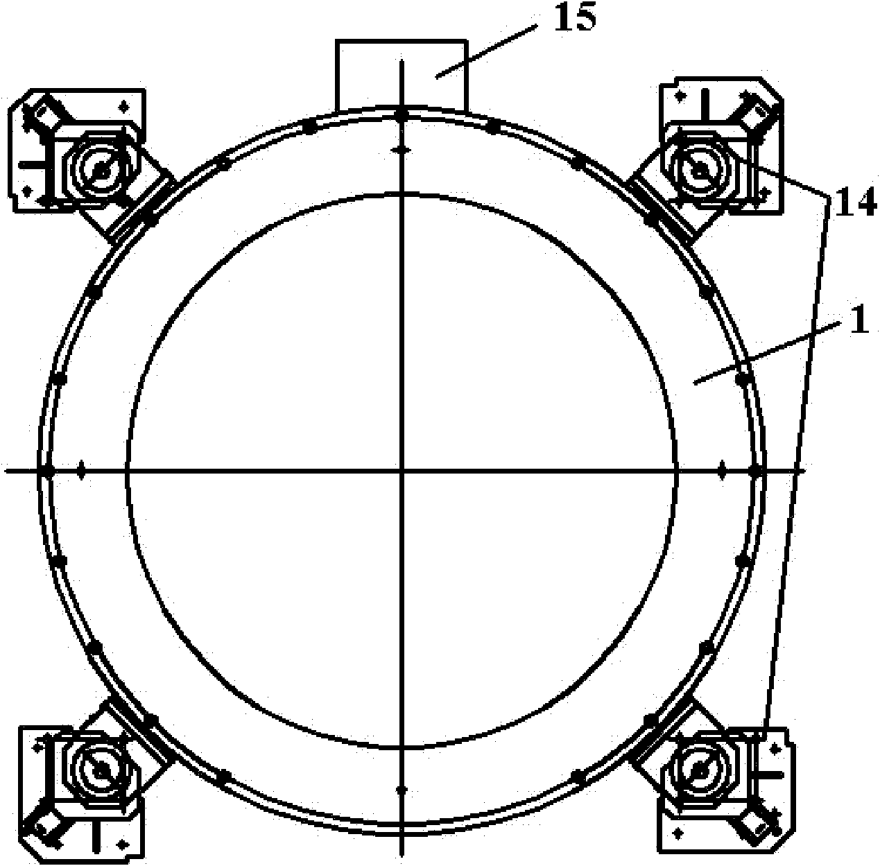
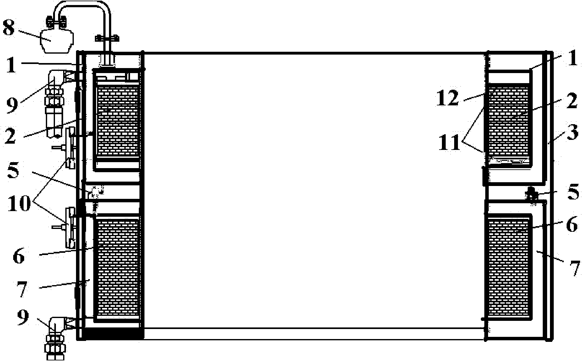
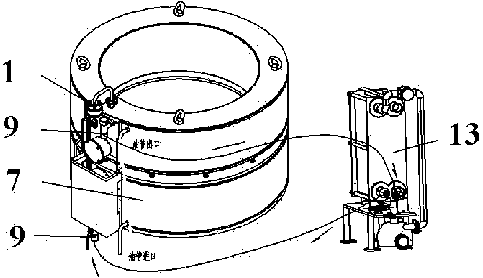
[0027] The large-diameter single crystal furnace hook-type electromagnetic field device in this embodiment includes two annular airtight chambers filled with cooling oil, and the annular airtight chambers are stacked up and down to form a hollow cylinder; each airtight chamber is located on the outside The semi-enclosed shielding body (upper coil shielding body 1 or lower coil shielding body 7), the inner cylinder 12 and two Er plates 11 are connected to each other in the form of welding, and are connected to the oil pump and oil cooler through pipelines. 13 together form a forced oil cooling system, and a water cooling jacket 3 is installed on the periphery of the shield body. The oil cooler 13 in this embodiment is a plate heat exchanger. The device has a positioning device for fixed installation, and the upper and lower airtight chamb...


PUM


Abstract

The invention relates to silicon single crystal material processing equipment, aiming at providing a hook-type electromagnetic field device of a full-diameter single crystal furnace. The hook-type electromagnetic field device comprises direct current coils for generating hook-type electromagnetic fields and at least two annular sealed containers filled with cooling oil, wherein the annular sealed containers are vertically overlaid to form a hollow cylinder shape; each sealed container is formed by mutually connecting a semi-enclosed shield located on the outer side, an inner cylinder located on the inner side and two yoke plates through welding, and the sealed containers as well as an oil pump and an oil cooler jointly form a forcible oil cooling system through pipelines; and the sealed containers are respectively and internally provided with one group of direct current coils formed by winding solid copper pipes. In the invention, because the two upper and lower coils are arranged in parallel, generated magnetic force lines are in axial symmetry distribution, meanwhile, the magnetic field intensity is continuously adjustable, and the axial and radial uniformity of a crystal bar is guaranteed so that the effect of controlling the content of oxygen in a single crystal is good. As bolts are used for connecting a bisectional structure, the transportation, dismounting, installation and debugging of the device provided by the invention are simpler and more convenient.

Description

technical field [0001] The invention relates to silicon single crystal material processing equipment, in particular to a hook-type electromagnetic field device matched with a large-diameter single crystal furnace. Background technique [0002] Silicon single crystal material is the most important semiconductor material and the material basis of the information society. Prompted by the rapid development of integrated circuits and stimulated by profit factors, the scientific research on silicon single crystal materials is bound to develop in the direction of high purity, high integrity, high uniformity and large diameter. However, in the production of single crystal by the Czochralski method, due to temperature gradient, gravity, rotation of the crucible crystal rod, etc., there is complex convection in the melt in the crucible, and the convection is more severe in the large-diameter single crystal furnace. These heat convection will lead to uneven axial and radial direction ...

Claims


Application Information

Patent Timeline
Patent Type & Authority Applications(China)
IPC IPC(8): C30B15/00C30B35/00
Inventor 曹建伟傅林坚石刚叶欣邱敏秀
Owner 杭州慧翔电液技术开发有限公司
Why Eureka
Try Eureka