Motor with cone disk brake

A technology of brakes and cones, applied in the direction of controlling mechanical energy, electrical components, electromechanical devices, etc., and can solve problems such as rotation

Inactive Publication Date: 2016-07-20
CHONGQING FUXIN GLASS
View PDF0 Cites 0 Cited by
  • Summary
  • Abstract
  • Description
  • Claims
  • Application Information

AI Technical Summary

Problems solved by technology

[0003] In view of this, the purpose of this invention is to provide a kind of motor with conical disc brake, to solve the problem that the rotor rotates under the action of inertial force when the motor stops

Method used


Image

  • Motor with cone disk brake

Examples


Embodiment Construction

[0010] The present invention will be further described below in conjunction with the accompanying drawings and embodiments.

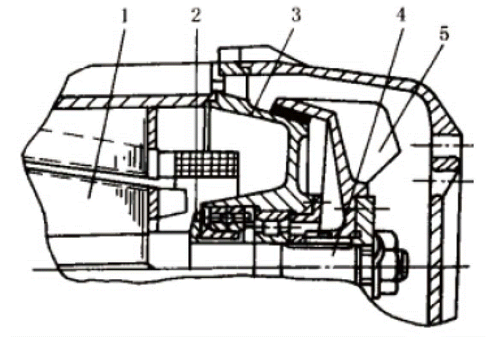
[0011] Such as figure 1 As shown, the present embodiment has a motor with a conical disc brake, including a rotor shaft 4, a conical rotor 1 fixed on the rotor shaft, and an outer conical disc 3 of the tail cap fixed at the end of the motor housing. The end of the shaft protrudes from the outer cone of the tail cap, and the end of the rotor shaft is fixedly connected with the inner cone brake disc 5 which is engaged with the outer conical surface of the outer cone of the tail cap, and the rotor shaft is also provided with The disc spring 2 whose end is pressed against the end surface of the outer cone of the tail cap; when the motor is stopped, the inner cone brake disc is pressed against the outer cone of the tail cap under the thrust of the disc spring.

[0012] This embodiment has a motor with a conical disc brake. When the motor is started, it will...


PUM


Abstract

The invention discloses a motor with a cone disk brake. The motor comprises a rotor shaft, a conical rotor and a tail-hood outer cone disk, wherein an inner conical surface brake disk engaged with an outer conical surface of the tail-hood outer cone disk is fixedly connected to the end part of the rotor shaft; a disk spring is also arranged on the rotor shaft; and the inner conical surface brake disk is pressed against the tail-hood outer cone disk under the action of thrust of the disk spring in a stopped state of the motor. According to the motor with the cone disk brake, when the motor is started, magnetic pull force for pushing the conical rotor to move along the axial direction is generated, and the magnetic pull force overcomes the thrust of the disk spring and pushes the inner conical surface brake disk to be separated from the tail-hood outer cone disk, so that the motor normally works; and when the motor is stopped, the magnetic pull force disappears, the disk spring pushes the rotor shaft to reversely move towards the right and the inner conical surface brake disk is pressed against the tail-hood outer cone disk, so that rotor braking is achieved; and the problem that motor becomes a generator to transmit electricity to a power grid since the rotor rotates under the action of inertial force can be solved.

Description

technical field [0001] The invention relates to a motor, in particular to a motor with a brake. Background technique [0002] When the motor is stopped, the rotor will continue to rotate for a certain period of time due to inertia, and the motor is in the state of generating electricity at this time. When the motor is in the power generation state, it will send electric energy into the grid, which will cause problems such as grid voltage fluctuations, and then affect other electrical equipment. There is no good way to solve this problem in the prior art. Contents of the invention [0003] In view of this, the object of the present invention is to provide a motor with a cone-disc brake to solve the problem that the rotor rotates under the action of inertial force when the motor is stopped. [0004] The motor with the conical disc brake of the present invention comprises a rotor shaft, a conical rotor fixed on the rotor shaft, and an outer conical disc of the tail cover fix...

Claims


Application Information

Patent Timeline
Patent Type & Authority Applications(China)
IPC IPC(8): H02K7/10
Inventor 陈雄
Owner CHONGQING FUXIN GLASS
Why Eureka
Try Eureka