Device for automatically calibrating bidirectional transmit-receive optical power of PON network equipment

A technology of automatic calibration and network equipment, applied in the direction of electromagnetic wave transmission system, electrical components, transmission system, etc., can solve the problems of time-consuming, high labor cost, many influencing factors, and many uncontrollable nodes, etc., to reduce external influence Factors, the effect of improving calibration accuracy and improving calibration efficiency

Active Publication Date: 2016-07-20
SHANDONG SENTER ELECTRONICS
View PDF6 Cites 6 Cited by
  • Summary
  • Abstract
  • Description
  • Claims
  • Application Information

AI Technical Summary

Problems solved by technology

[0011] 1. The operation steps are cumbersome and the efficiency is low;
[0012] 2. There are many uncontrollable nodes and many influencing factors
[0014] The above factors affect the change of t

Method used


Image

  • Device for automatically calibrating bidirectional transmit-receive optical power of PON network equipment
  • Device for automatically calibrating bidirectional transmit-receive optical power of PON network equipment
  • Device for automatically calibrating bidirectional transmit-receive optical power of PON network equipment

Examples


Embodiment 1

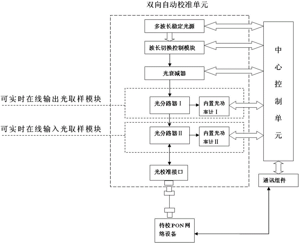
[0059] like image 3 As shown, the PON network equipment bidirectional optical power automatic calibration device of the present invention includes at least one set of bidirectional automatic calibration unit and a central control unit, the bidirectional automatic calibration unit is connected to the central control unit, and the bidirectional automatic calibration unit includes sequentially connected The optical adjustment module, the optical sampling module capable of real-time online output and the optical sampling module capable of real-time online input, the optical sampling module capable of real-time online input are connected to the optical calibration interface, and the optical calibration interface is connected to the PON network equipment to be calibrated.

[0060] Wherein, the real-time online output optical sampling module includes an optical splitter 1, a built-in optical power meter 1, the input end of the optical splitter 1 is connected to the optical adjustment...

Embodiment 2

[0084] like Figure 4 As shown, in this embodiment, the real-time online output optical sampling module and the real-time online input optical sampling module share a bidirectional optical splitter, and the output ends of the bidirectional optical splitter are respectively connected to the built-in optical power meter I and the built-in optical power meter II One input end of the bidirectional optical splitter is connected to the optical calibration interface, the other input end is connected to the optical adjustment module, the built-in optical power meter I and the built-in optical power meter II are respectively connected to the central control unit, and other structures are the same as in embodiment 1. The difference between this solution and the previous solution is that the optical sampling module capable of real-time online output and the real-time online input optical sampling module share an optical splitter.

Embodiment 3

[0086] like Figure 5 As shown, in this embodiment, on the basis of Embodiment 1, the optical splitter II is replaced by an optical path switching device, such as an optical switch. The optical switch is connected to the optical link in a time-sharing manner, and is switched to Built-in optical power meter II.


PUM


Abstract

The invention belongs to the field of bidirectional transmit-receive optical power calibration of single-fiber bidirectional optical network equipment, and relates to a device for automatically calibrating bidirectional transmit-receive optical power of PON network equipment. The device comprises at least a set of a bidirectional automatic calibration unit and a central control unit, wherein the bidirectional automatic calibration unit is connected with the central control unit, the bidirectional automatic calibration unit comprises a light adjusting module, a real-time on-line output light sampling module and a real-time on-line input light sampling module, and the real-time on-line input light sampling module is connected with a light calibration interface. Bidirectional real-time calibration of a same light source is realized, the accuracy is greatly improved, consistency of product is ensured, manual intervention is minimized, productivity is increased, cost is lowered, and use performance of equipment is improved.

Description

technical field [0001] The invention belongs to the field of calibration of bidirectional receiving and receiving optical power of single-fiber bidirectional optical network equipment, and in particular relates to an automatic calibration device for bidirectional receiving and receiving optical power of PON network equipment. Background technique [0002] PON (Passive Optical Network) access network technology is recognized in the industry as the best solution for FTTx, and it is also the main access method of fiber-to-the-home. The scale of the optical network and the number of terminals are huge. This technology can enable multiple users to share a single Root optical fiber, so that no active components are used in the optical distribution network (ODN), that is, no "optical / electrical / optical" conversion is required. This point-to-multipoint architecture greatly reduces network installation, management and maintenance. cost. [0003] In the PON system (GPON, EPON, etc.),...

Claims


Application Information

Patent Timeline
IPC IPC(8): H04B10/073H04B10/079
CPCH04B10/0731H04B10/07955
Inventor 张海峰蔡富东李全用刘在平张晓宇王景吕昌峰崔利
Owner SHANDONG SENTER ELECTRONICS
Why Eureka
Try Eureka