Water-land optical communication network architecture and communication method based on interconnection between underwater visible light communication network units (UVNU) and fiber

A technology of visible light communication and optical communication network, which is applied in the field of water and land optical communication network architecture and communication, which can solve the problems of short communication distance, inability to transmit large-bandwidth data, and difficult maintenance of underwater network centers, so as to facilitate maintenance and avoid communication quality Falling effect

Active Publication Date: 2016-07-20
BEIJING UNIV OF POSTS & TELECOMM
View PDF7 Cites 8 Cited by
  • Summary
  • Abstract
  • Description
  • Claims
  • Application Information

AI Technical Summary

Problems solved by technology

[0007] In order to overcome the short communication distance of the underwater VLC, the large bandwidth data cannot be transmitted to the underwater long-distance collaborative work node and the water terminal for real-time processing, and the diffic...

Method used


Image

  • Water-land optical communication network architecture and communication method based on interconnection between underwater visible light communication network units (UVNU) and fiber
  • Water-land optical communication network architecture and communication method based on interconnection between underwater visible light communication network units (UVNU) and fiber
  • Water-land optical communication network architecture and communication method based on interconnection between underwater visible light communication network units (UVNU) and fiber

Examples


Embodiment Construction

[0037] The specific implementation method will be described in detail below in conjunction with the accompanying drawings.

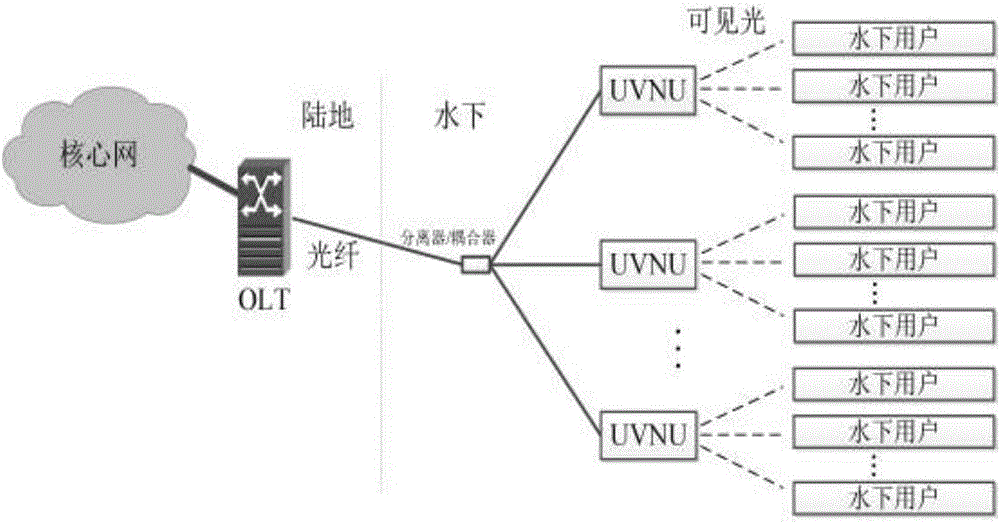
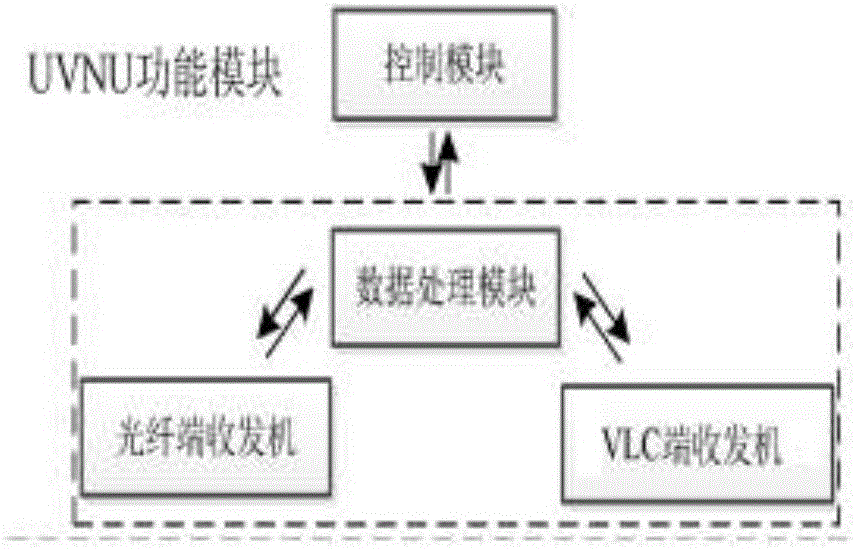
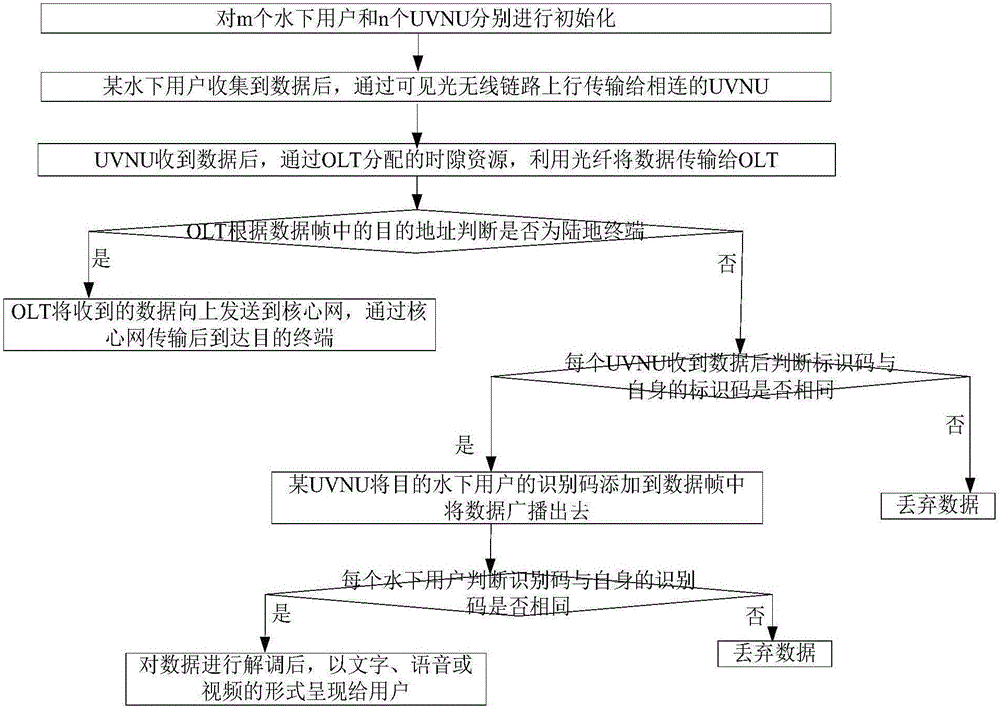
[0038] The present invention utilizes the large bandwidth and long distance of traditional passive optical network (passive optical network, PON) and the characteristics of large bandwidth and fast transmission rate of visible light communication (visible light communication, VLC) technology, and proposes an underwater long-distance communication between users. And the network structure for communication between underwater users and land users. The optical line terminal (optical line terminal, OLT) in the PON network is placed on land, and the original function is maintained. The optical network unit (ONU) part is redesigned as an LED node and placed underwater, using VLC technology to communicate with underwater users. This part is renamed as underwater VLC network unit (underwaterVLCnetwork unit, UVNU). In order to improve the communication quality de...


PUM


Abstract

The invention discloses a water-land optical communication network architecture and a communication method based on interconnection between underwater visible light communication network units (UVNU) and a fiber. The communication network architecture comprises an optical line terminal (OLT), a separator/coupler, the UVNUs and underwater users, wherein the OLT is connected with a core network and arranged on the land; and the separator/coupler, the UVNUs and the underwater users are all arranged underwater. The communication method comprises steps: the network is firstly initialized, and data collected by a certain underwater user are transmitted to the connected UVNU in an uplink mode and then transmitted to the OLT; if the OLT recognizes the destination address to be the land terminal, the data are transmitted to the core network; or otherwise, the OLT adds the identification code of the UVNU at the destination address to a data frame, and the data frame is broadcasted to the UVNU; the UVNU judges whether the identification code is the same as that of the UVNU itself, and if not, discarding is carried out, or otherwise, the UVNU broadcasts the data frame with the identification code of the destination underwater user to the underwater user; and finally, the underwater user judges whether the identification code is the same as that of the underwater user himself or herself, if yes, the data are demodulated, or otherwise, the data are discarded.

Description

technical field [0001] The invention belongs to the field of optical communication, in particular to an amphibious optical communication network framework and a communication method based on the interconnection of underwater visible light communication network units and optical fibers. Background technique [0002] With the continuous development of underwater applications, people have put forward higher requirements for the capacity of underwater transmission links. [0003] At present, acoustic communication technology is the most widely used underwater communication technology, with an acoustic propagation rate of 1500m / s and a large transmission delay. Using acoustic communication technology, data can be transmitted for several kilometers or even tens of kilometers, and the transmission capacity is tens to hundreds of kHz. However, acoustic communication technology cannot satisfy the transmission of large-bandwidth underwater signals; and the very mature radio frequency...

Claims


Application Information

Patent Timeline
IPC IPC(8): H04B10/116H04B10/25H04B10/27H04B13/02H04L12/46
CPCH04B10/116H04B10/2589H04B10/271H04B13/02H04L12/46
Inventor 黄治同李伟纪越峰
Owner BEIJING UNIV OF POSTS & TELECOMM
Why Eureka
Try Eureka