Conveyor roller and conveyor system with moisture protection

A technology of conveying equipment and conveying rollers, which is applied in the direction of conveyors, conveyor objects, transportation and packaging, etc. It can solve the problems of equipment control system rust, corrosion, influence, etc., and achieve the effect of ensuring trouble-free operation

Active Publication Date: 2016-07-20
TGW MECHANICS GMBH
View PDF5 Cites 6 Cited by
  • Summary
  • Abstract
  • Description
  • Claims
  • Application Information

AI Technical Summary

Problems solved by technology

The problem faced in the use of conveying rollers or conveying equipment is that these conveying rollers or conveying equipment are subjected to dirt and dripping liquid
The result can be short-term damage such as short circuits and malfunctions of the plant control system as well as long-term damage in the form of, for example, rust, corroded contacts and the like

Method used


Image

  • Conveyor roller and conveyor system with moisture protection
  • Conveyor roller and conveyor system with moisture protection
  • Conveyor roller and conveyor system with moisture protection

Examples


Embodiment Construction

[0025] As an introduction, the first thing to note is that in the various embodiments described in different descriptions, the same components are provided with the same reference numerals or the same component names. Among them, the disclosure contained in all the descriptions can be used according to the meaning. To the same parts provided with the same reference signs or the same component names. Furthermore, the orientation descriptions selected in the description, such as up, down, side, etc., are all relative to the direct description and the drawings shown, and when the orientation changes, it can be transferred to a new orientation according to the meaning. . In addition, individual features or combinations of features from the different shown and described embodiments can also constitute an independent, inventive or inventive solution.

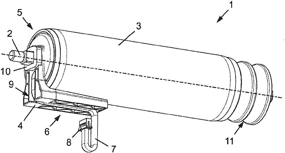
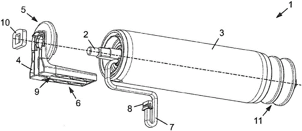
[0026] figure 1 with 2 Shown is an oblique view of an exemplary conveying roller 1 ( figure 1 ) And exploded view ( figure 2 ). in f...


PUM


Abstract

Disclosed is a conveyor roller (1) which comprises a shaft (2), a roller body (3) which is mounted to be rotatable about the shaft (2), and a protective cap (4). The protective cap (4) has a disc-shaped first section (5) for covering the interior of the roller body (3), which first section (5) is arranged fixedly with respect to the shaft (2) and is oriented normally with respect thereto, and a channel-like or roof-like second section (6) which is arranged obliquely with respect to the shaft (2) and runs over a part length of the roller body (3) so as to be spaced apart radially from the latter. Furthermore, a conveyor system with a conveyor roller (1) is disclosed, in which conveyor system a connector cable (7) of the conveyor roller (1) is guided in a curve or a loop to an electrical interface (8, 17) with a connector box of the conveyor system, wherein the lowest point of the curve/the loop is located below said interface (8).

Description

Technical field [0001] The present invention relates to a conveying roller having a shaft and a roller body rotatably supported around the shaft. Furthermore, the present invention relates to a conveying device including a conveying roller having a shaft, a roller body rotatably supported around the shaft, a motor for driving the roller body provided in the roller body, and a slave roller The connecting cable drawn from the body and electrically connected to the motor. In addition, the conveying equipment includes: two frame profiles extending at a distance from each other, and a conveying roller is arranged between the two frame profiles; power and / or data wires extending along one frame profile and wiring arranged on the frame profile The junction box is electrically connected with the power supply and / or data wires and with the connecting cable. Background technique [0002] Conveying rollers and conveying devices of the type described are basically well-known and are used i...

Claims


Application Information

Patent Timeline
Patent Type & Authority Applications(China)
IPC IPC(8): B65G23/08B65G39/09B65G13/06B65G13/11
CPCB65G39/09B65G13/06B65G13/11B65G23/08
Inventor J·赖施尔
Owner TGW MECHANICS GMBH
Why Eureka
Try Eureka