Rotary tiller with tilting cutter

A technology for rotary tillers and knives, which is applied in the field of rotary tillers with inclined knives, can solve problems such as relying on manual rescue, no traction mechanism, and the inability of rotary tillers to provide lifting force for rotary tillers. Effects of labor intensity, increased tillage depth, and improved soil tillage efficiency

Inactive Publication Date: 2016-07-27
重庆美澳机械制造有限公司
View PDF5 Cites 5 Cited by
  • Summary
  • Abstract
  • Description
  • Claims
  • Application Information

AI Technical Summary

Problems solved by technology

Rotary tillage mainly uses the rotation of the cutter to cut the land to complete related operations. In mountainous and hilly areas, small gasoline engines or small diesel engines are usually used as a series of walking farming farming machinery powered by small gasoline engines. This small rotary tiller Generally, there is no special traction mechanism. When working, the reaction force generated when the tool is rotated to cut the soil is used as the traction force to move forward. This reaction force is relatively small when cultivating muddy land or deep water fields, which is not enough. When the traction machine moves forward, a deep sink will occur. Once a deep sink occurs, there is no other way than manual rescue, and a small number of rotary tillers equipped with traction wheels and other traction mechanisms have the axis of the rotary tiller along the forward direction. It is set horizontally, therefore, the height of the rotary tiller relative to the ground is relatively high. When cultivating the soil, the soil tillage depth is relatively shallow, and it is difficult to reach the tillage depth required for planting. Therefore, it is necessary to use a rotary tiller with a long rotary tiller blade. Only the cutting tool can meet the requirement of plowing depth. In addition, since the rotary tiller cannot provide upward lifting force for the rotary tiller, when the traction wheel is deeply sunken, manual rescue can only be relied on.

Method used


Image

  • Rotary tiller with tilting cutter
  • Rotary tiller with tilting cutter
  • Rotary tiller with tilting cutter

Examples


Embodiment Construction

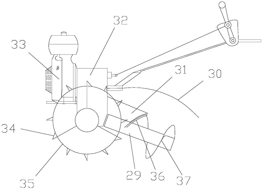
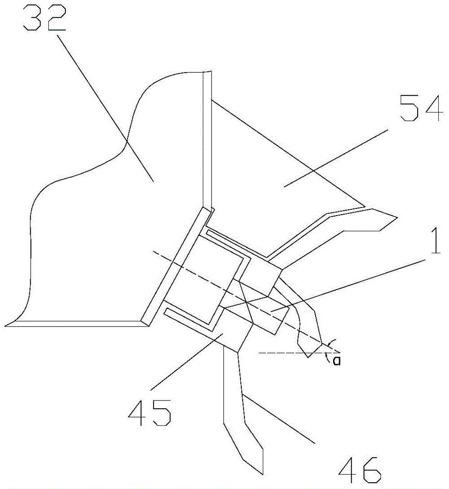
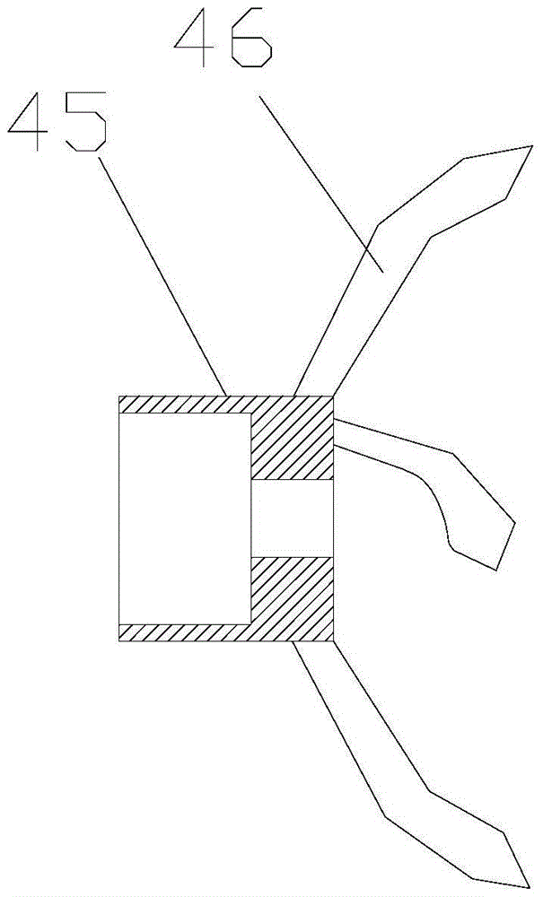
[0037] figure 1 It is a structural schematic diagram of the present invention, as shown in the figure, the inclined cutter rotary cultivator of this embodiment includes a power unit 32, a traction wheel 35, a rotary tiller and is used to receive the power output by the power unit 32 and transmit the power respectively To the traction wheel 35 and the transmission box 32 of the rotary tiller; the axis of the rotary tiller is inclined downward so that the horizontal direction forms an included angle, and the range of the included angle α is: 20°<α<40°; in this embodiment The middle power unit 32 adopts a small-sized gasoline engine, and its output shaft is connected with the input shaft of the transmission box 32. The transmission box 32 stretches out the traction drive shaft 28 along the lateral direction of the rotary tiller to drive the traction wheel 35 to rotate, and the rearward direction along the longitudinal direction of the rotary tiller Stretch out cutter drive shaft ...


PUM


Abstract

The invention discloses a rotary tiller with a tilting cutter. The rotary tiller comprises a power device, a traction wheel, a rotary tilling knife and a transmission case which is used for receiving power output from the power device and separately transmitting the power to the traction wheel and the rotary tilling knife. The axis of the rotary tilling knife is arranged along the direction of advance of the rotary tiller, the outer end of the rotary tilling knife tilts down so as to enable the axis of the rotary tilling knife to form an included angle with the horizontal plane, and thus the tilth of the rotary tiller is effectively increased; and meanwhile, during the soil cutting of the rotary tilling knife, a counteracting force along the axial direction of the cutter will be generated and has a pushing force enabling the rotary tiller to advance and a lifting force enabling the rotary tiller to rise, so that the rotary tiller can be effectively prevented from being deeply trapped during the tilling of marshy lands or deepwater fields.

Description

technical field [0001] The invention relates to the field of soil tillage machinery, in particular to a rotary tiller with inclined cutters. Background technique [0002] In the prior art, agricultural mechanized production mainly uses plowing, harrowing and rotary plowing for soil cultivation. Plowing mainly uses a traction mechanism to pull the plowshares to turn the land to achieve the purpose of plowing. Harrowing mainly uses traction. The mechanism pulls tools such as disc harrows, spike-toothed harrows, or paddy field star harrows to cultivate the soil surface, which is usually a finely broken and leveled intensive cultivation operation on the land after plowing. Rotary tillage mainly uses the rotation of the cutter to cut the land to complete related operations. In mountainous and hilly areas, small gasoline engines or small diesel engines are usually used as a series of walking farming farming machinery powered by small gasoline engines. This small rotary tiller Gen...

Claims


Application Information

Patent Timeline
IPC IPC(8): A01B49/04A01B33/06A01C5/06
CPCA01B33/06A01B49/04A01C5/064
Inventor 夏文万陈世福王吉龙
Owner 重庆美澳机械制造有限公司
Why Eureka
Try Eureka